The National Instruments CompactRIO Controller, cRIO-9074, is an embedded controller that is perfect for advanced monitoring and control. Since it is an electronic device, the cRIO-9074 requires a DC power supply to work. The ideal power supply for this purpose is the PS-15.
The PS-15 is an industrial power supply that is used to power CompactRIO systems, CompactDAQ systems, and many more. This component takes in an input of 100 VAC to 240 VAC and supplies an output of 24 VDC, 5 A to the cRIO-9074. However, for this setup to work, you need to carry out all the connections properly.
This blog post covers the process of setting up and powering the PS-15, and subsequently, the cRIO-9074.
How to Power the PS-15
The first step in setting up the cRIO-9074 is connecting the PS-15 to an AC power source.
Input
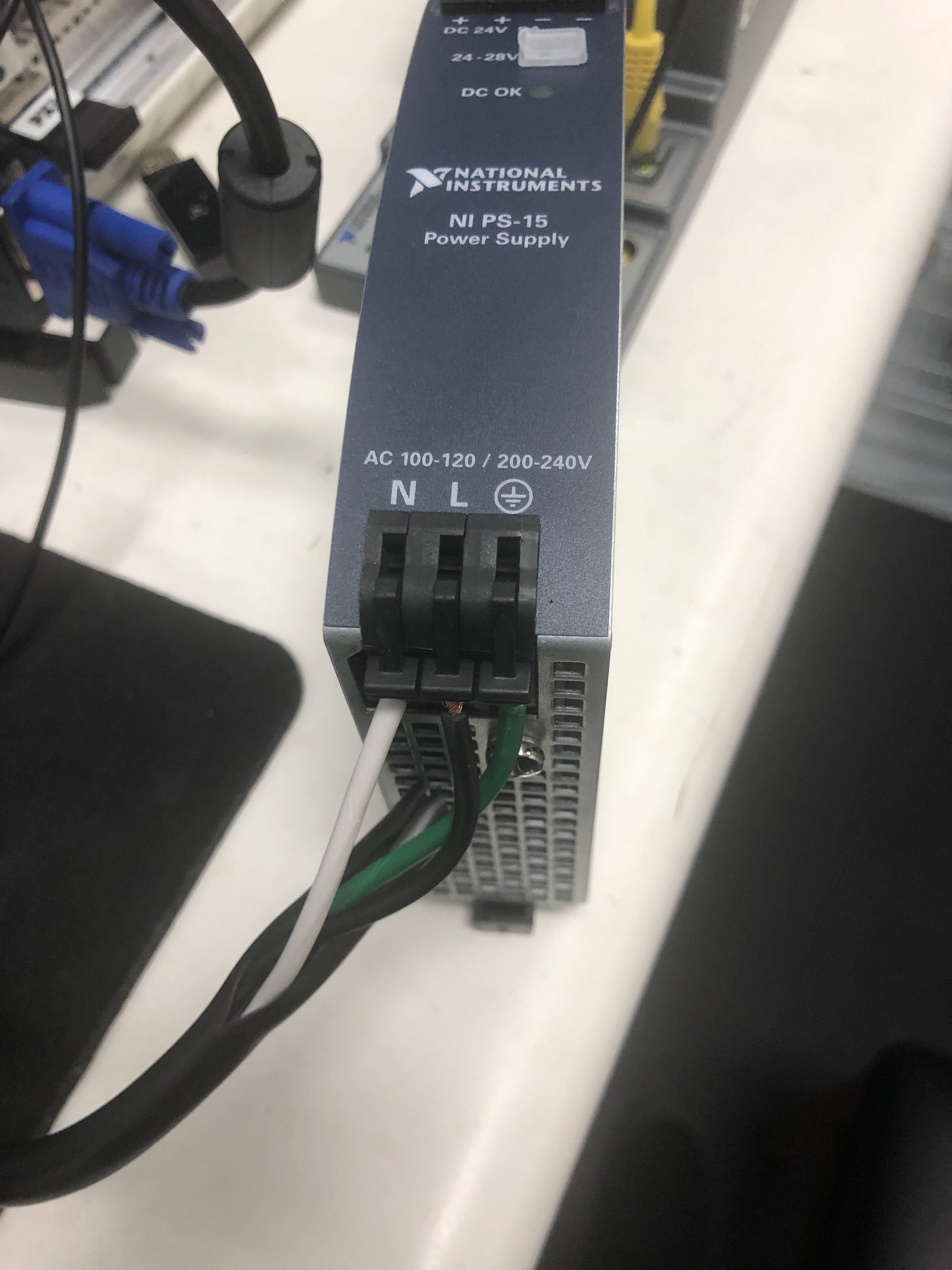
The PS-15 has three input terminals; the Live terminal labeled “L,” the Neutral terminal labeled “N” and the Protective Earth (PE) terminal labeled with the electrical grounding symbol. These terminals correspond with the live, neutral, and earth ports of a grounded electrical socket.
To connect the PS-15 to the power source, strip the ends of a standard 300 V (16 AWG) cable to expose the three wires inside. These wires are color-coded according to the terminals or ports to which they are to be connected; white for neutral, black for live, and green for earth. Note that the color coding for different cables may vary. The most common variations are blue (neutral), red/brown (live), and green (earth); and black (neutral), red (live), and yellow/green (earth).
After exposing the wires, strip each wire by about 7 mm (0.275 in) to expose the copper inside. Connect the exposed ends of the three wires to the PS-15 input terminals by lifting the terminal levers and inserting the wires into their corresponding input terminals. The live wire to the terminal labeled “L”, the neutral wire to the terminal labeled “N”, and the earth wire to the last terminal. Move the levers back down to the closed position and check that all your wires are tightly connected. If you are using stranded wire, ensure that all the strands are inside the terminal before you close it.
Next, strip the other ends of the wires as described above. These ends go into the MAINS power source. Make sure that the power source is switched off before carrying out any connections. It is recommended that you first connect the wires to a plug before connecting them to the MAINS. Also, ensure that the wires from the neutral, live, and earth input terminals are connected to their corresponding neutral, live, and earth ports in the power source. After these connections, switching on the power source will turn on the PS-15 and its indicator light. However, keep the power source off until you’ve completed the connections in the PS-15 output terminals.
Output
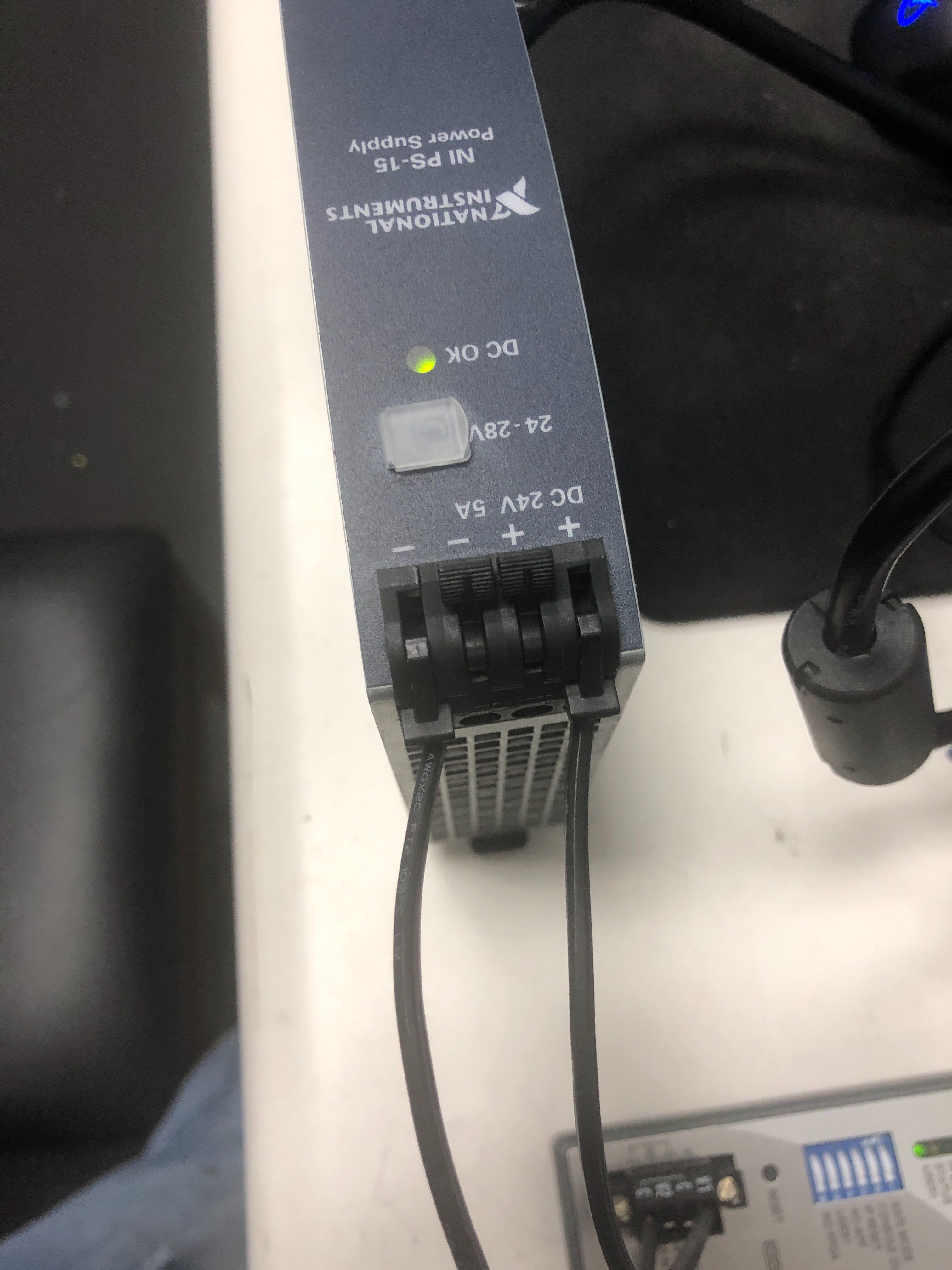
The PS-15 has four output terminals: two positives, labeled “+” and two negatives labeled “-.”To get power out of the PS-15, connect two wires with their ends exposed to the output terminals, one to a positive terminal and the other to a negative terminal. The other ends of these two wires are to be connected to the cRIO-9074.
How to Power CompactRIO
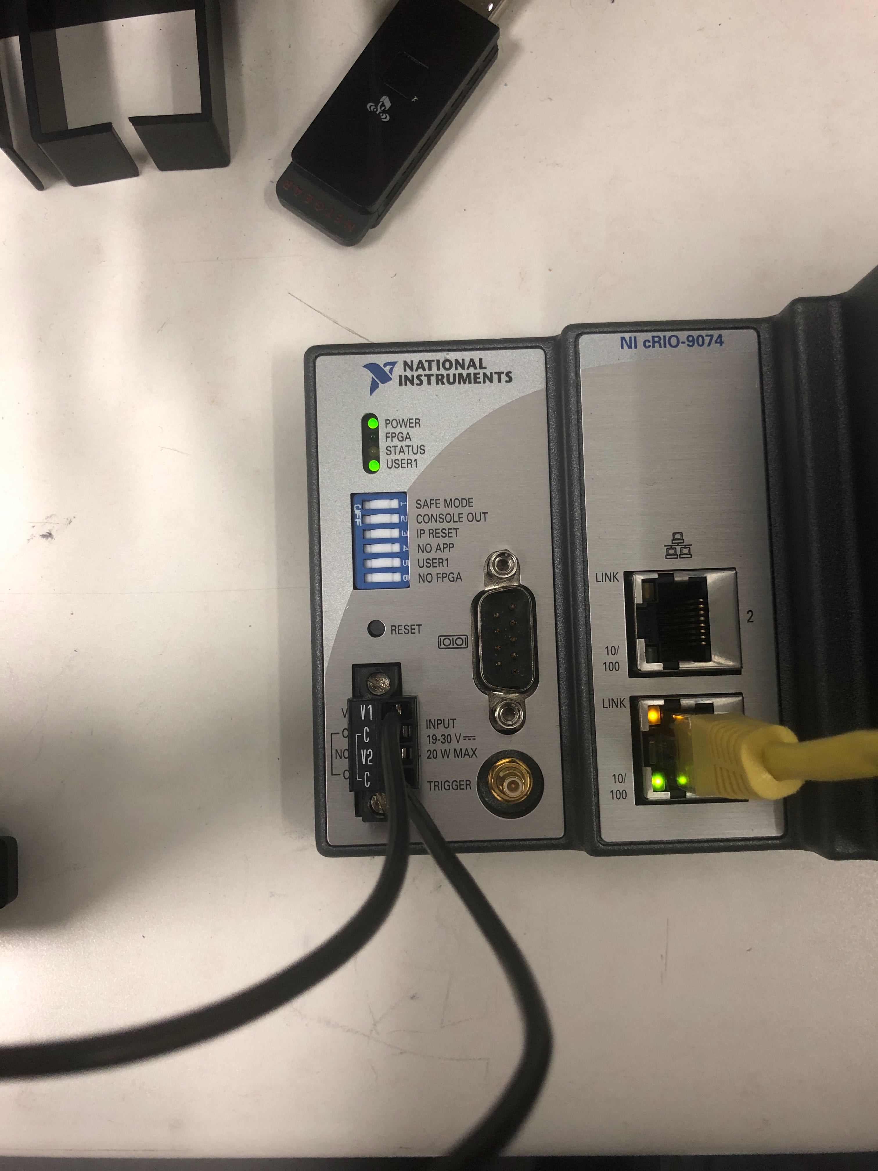
Fit an adapter (power controller) with four terminals into the power terminals of the CompactRIO Controller and screw it in. The adapter’s four terminals are labeled “V1,” “V2,” “C,” and another “C.” Take the ends of the two wires coming from the output terminals of the PS-15 and insert them into the terminals of the adapter that is fitted to the cRIO-9074. The wire from the positive (+) terminal of the PS-15 is connected to either of the terminals labeled “V1” or “V2,” while the wire from the negative (-) terminal is connected to either of the terminals labeled “C.” You may now switch on the power source to turn on the whole setup and you are good to go!
IP Reset
For the cRIO-9074 to function properly at MAX, you need to carry out an IP reset. To do this, flip the IP reset switch to the “ON” position, then press and release the reset button. After this, flip the switch back and refresh the component MAX.


