Modular Systems > National Instruments > GPIB Instrument Control Modules


Pictures shown are a representation. Actual item may vary if no part number is provided on quote request.
✔ Same Day Calibration Available
✔ 2-3 Year Warranty Included
✔ Free Ground Shipping
Or speak to a sales representative for additional information:
Phone:
1-800-915-6216Email:
sales@apexwaves.comGPIB-120B Request for Availability
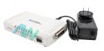
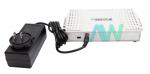
GPIB-120B, Software-Transparent, High-Speed Bus Isolator/Expander
National Instruments GPIB-120B GPIB Expander/Isolator
The NI GPIB-120B (Part Numbers: 779651-01, 779651-04, 779651-06, and 779651-07) is a GPIB Bus Expander/Isolator. This model is fully compatible with IEEE 488.1 and IEEE 488.2 standards. With this model, the user can expand the limit of allowable devices on the GPIB bus to as many as 28. Thus, this Expander/Isolator can be used in a variety of test and measurement systems.
The GPIB 120B Bus Isolator Expander offers great isolation capabilities because it can provide up to 2,500 VDC of isolation (non-continuous) between the GPIB ports, the power supply, and every individual GPIB port. With this model, bidirectional expansion of GPIB system devices can be achieved where talkers, listeners, and controllers can exist on either side of the expansion.
The NI GPIB-120B can effectively eliminate induced common-mode noise and ground loop noise by operating as an isolating bearer between instruments and an IEEE 488 bus controller. Each GPIB-120B enables the user to add as many as 14 additional devices to the GPIB bus. Functionally, this device operates transparently. Therefore, the GPIB control and communication programs that work with the unexpended system can be utilized with an expanded system as well.
This Expander/Isolator offers two data transfer modes: buffered mode and unbuffered mode. In its standard configuration, unbuffered transfer mode is set as the default switch setting. However, users can select their desired data transfer mode by using the switch provided on the back of the unit. The NI GPIB-120B comes featured with eight data lines (DIO1, DIO2, DIO3, DIO4, DIO5, DIO6, DIO7, and DIO8) and three hardware handshake lines.
| Model | GPIB-120B |
|---|---|
| Manufacturer | National Instruments |
| Part Numbers | 779651-01, 779651-04, 779651-06, and 779651-07 |
| Type | GPIB Expander/Isolator |
| Compatibility | IEEE 488.1 and IEEE 488.2 |
| Continuous Isolation | 60 VDC |
| Maximum IEEE 488 Bus Transfer Rates | Buffered Mode: Up to 1.2 MB/s Unbuffered Mode: Up to 450 kB/s |
| Dimensions | 6.30 by 3.68 by 1.24 in. |
| Weight | 8.64 oz. |
| Warranty | 2-3 Year Warranty |
| GPIB-120B Manual | User Manual and Maintenance Manual Available for Download |
| Price | Contact a sales representative for a quote. |
Associated part numbers for GPIB-120B:
National Instruments GPIB-120B Frequently Asked Questions
Question: What are the differences between the four part numbers for the GPIB 120B Bus Isolator Expander?
Answer: The four part numbers for the GPIB 120B Bus Isolator Expander have varying power inputs. The first part number, 779651-01, is U.S. 120 VAC. Next, part number 779651-04 is Universal Euro 240 VAC. Part number 779651-06 is U.K. 240 VAC. The last part number, 779651-07, is Japan 100 VAC.
Question: What is the input voltage range of the GPIB-120B?
Answer: The input voltage range of the GPIB-120B is 12 to 18 VDC.
Question: What is required to operate the NI GPIB-120B?
Answer: The following items are required to operate the NI GPIB-120B: a 10-18 VDC 9 W Power Supply and standard GPIB cables to link both sides of the GPIB-120B to buses on either side.
Question: Which rack-mount kit can be utilized with the GPIB-120B?
Answer: The Rack-mount kit (Part Number: 194906-01) and the DIN rail mount kit (Part Number: 779689-01) can be utilized with the GPIB-120B.
Delivery:
Warranty:
All of our products are covered by our Apex Waves Warranty.
✓ 3 Year Warranty - New Surplus Parts
✓ 2 Year Warranty - Refurbished Parts
Returns:
No hassle return policy.
Dedicated customer service team.
Payment:


Quick Quotes:
Receive Price & Availability Today!
Calibration:
Ask About Our Tiered Calibration Levels
Option & Modules:
Confirm Your Requirements or Versions
Repair:
Cost & Lead Time Available Upon Request for Service
Repair Evaluation: $150
Common Typos: