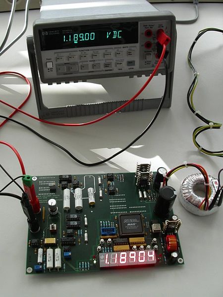
The higher the ohms/volt rating of a voltmeter, the less the voltmeter will upset circuit conditions. And the less circuit conditions are upset, the more accurate the reading will be. Most of the higher-end voltmeters and multimeters available now are rated at about 20,000 ohms/volt; more accurate voltmeters are rated at 100,000 ohms/volt. In some of the high-resistance circuits found in some present-day equipment, however, even a meter rated at 20,000 ohms /volt will greatly upset circuit conditions, and result in an incorrect reading. While a 100,000 ohms/voltmeter will give more accurate readings, even more accuracy is needed with some circuits. To overcome this problem, a device with a high ohms/volt rating called an electronic voltmeter was developed.
A typical electronic voltmeter has an ohms/volt rating of 11 megohms. Because of this high rating, the electronic voltmeter draws an extremely small current from the circuit under test and has a small effect on circuit conditions. Consequently, the electronic voltmeter provides much more accurate voltage readings in high-resistance circuits than pointer voltmeters and multimeters without electronic amplifiers.

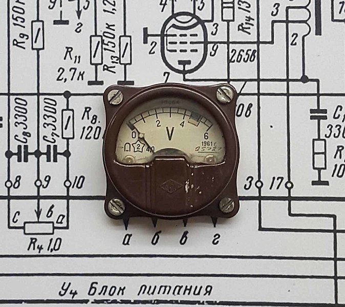
The electronic amplifiers used in electronic voltmeters can have different characteristics depending on the amplifying elements used. The original amplifiers used electron tubes, which were then called vacuum tubes. As semiconductors became more popular and inexpensive, junction or bipolar transistors were used. Then field effect transistors (FETs) were used more often because they had input impedances like electron tubes. Operational amplifiers, which are stable and less expensive, and have high input impedances are used more frequently with digital meters.

Since many amplifier types have different impedance characteristics, the electronic voltmeters utilize a resistor input network as a buffer between the circuit being tested and the amplifier stage. This network is a voltage divider or attenuator network. The voltage under test is always applied across the whole network, which typically has a total resistance of 11 megohms. The voltage is tapped down, with a range switch, to keep the input voltage to the amplifier under 1 volt.
Originally, electron tubes were used as amplifiers because they had high input resistances. But they were expensive, took up a lot of room, generated a lot of heat, were fragile, and were prone to failure. As transistors became perfected, they replaced tubes in most applications. But the initial transistor types were junction or bipolar transistors, which had low input resistances. More amplifier stages or junction transistors were needed to isolate the meter circuits from the divider network. FETs, which have input resistances like those of tubes, are now used almost exclusively as input amplifiers and can be combined with junction transistors in the following stages.
Operational amplifiers (op-amps), which combine the transistor and many of the resistor and capacitor components of the complete amplifier stage on a chip, also come in versions that have high-input resistances, and have become popular as meter amplifiers, especially in digital meters.
Sources:


