Introduction to Legacy Test Equipment

legacy test equipment - woman working in lab

While technology is constantly evolving and innovation is the name of the game, one everlasting component remains a constant: test equipment. These steadfast tools quietly warrant the reliability and quality of products experimented with for decades. 

So, what exactly is legacy test equipment, and why is it important? In this article, we’ll discuss the ins and outs of test equipment, what industries it fits into, and how it may be relevant to you

Continue reading “Introduction to Legacy Test Equipment”

Methods For Measuring Currents

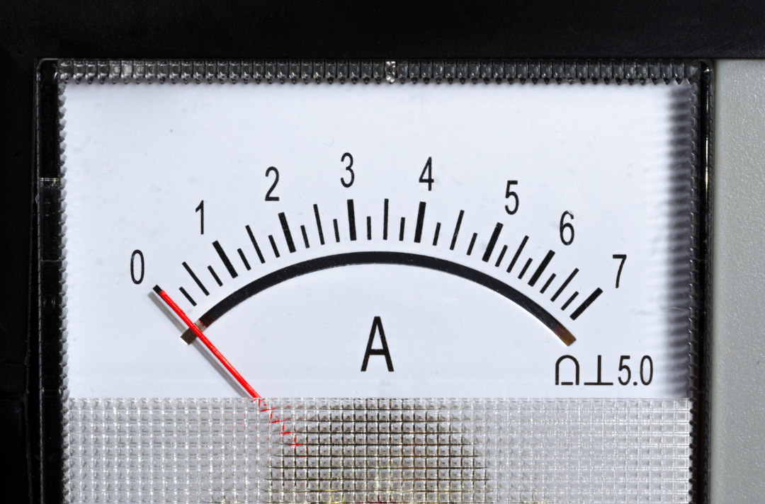
Closeup of the screen of an analog ammeter

Last week, we published a blog post going over the tools and methods used to measure electrical voltage in various situations. This week, we are taking a look at tests for measuring electrical currents- an essential step in electronic equipment maintenance that can identify the root cause of any failures and malfunctions. We will look at how to use ammeters, the importance of wire size, and how to test currents in power lines, heater motors, and air conditioners.

Continue reading “Methods For Measuring Currents”

Methods For Testing Voltages

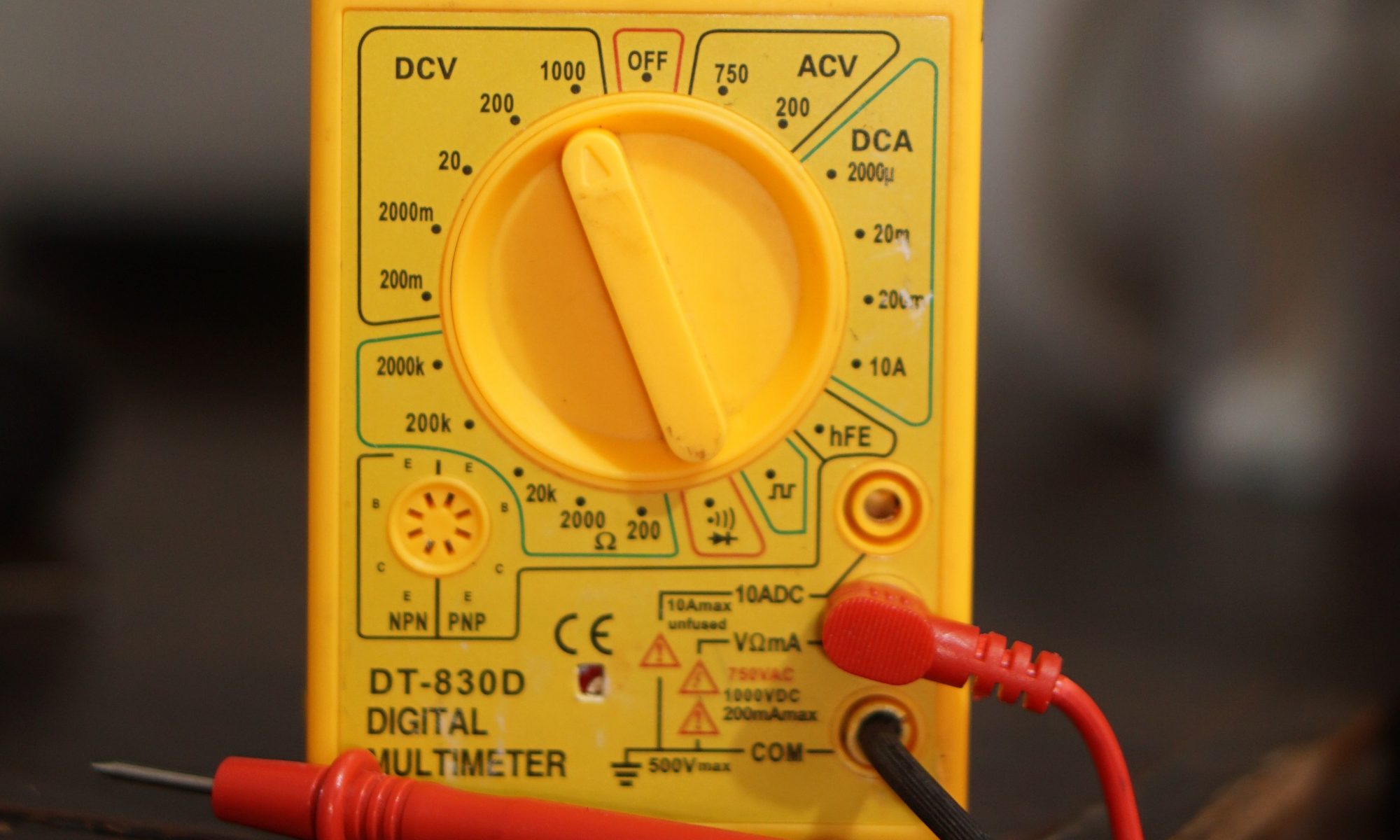
Closeup of person holding a yellow digital multimeter to check voltages of wiring

Measurements of electrical voltage are used to determine the possible differences in electric charge between two different points in an electric circuit. This data makes it possible to ascertain how much power is being used by a specific object, compared to how much power is available in the circuit. Since it allows us to ensure that an electrical circuit is operating both correctly and safely, this information is essential for the design, installation, and operation of electrical systems.

Continue reading “Methods For Testing Voltages”

Identifying Harmonic Distortion

Ever since the first generators, harmonics have been a part of power systems. However, we now live in an era of power that is defined by non-linear loads. Equipment for powering computers, electronic ballasts, and VFDs are among the electronic power supplies that are used now more than ever. Unchecked harmonic distortion in these electrical equipment systems can result in damage and hazards such as overheating. Not only does this affect power quality, but it can become costly to fix. The question then becomes: do you know how to correctly measure the waveforms of your equipment while taking harmonic distortion into account?

Continue reading “Identifying Harmonic Distortion”

Calibrating and Measuring Accuracy in Analog Meters

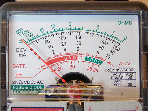
Closeup of analog meter screen

All electromagnetic current meters function on the basis that the intensity of the magnetic field around a coil is proportional to the amount of current flowing through it. Whether the meter you are using is alternating current (AC) or direct current (DC), knowing what to expect from the different meter movements is essential for correct calibration and accurate measurements.

Continue reading “Calibrating and Measuring Accuracy in Analog Meters”

Ohmmeters: Measuring Resistance

Multimeters are current meters, voltmeters, and ohmmeters contained in one case. There are separate current, voltage, and resistance circuits interconnected by switches and they share the same meter movement. A function switch is utilized to choose the type of measurement: position 1 is for de volts and resistance, position 2 is for de and ac current, and position 3 is for ac voltage. The jack on the right, the COMMON jack, is used for all measurements. For every type of measurement, the range switch is set for the correct scale reading. Positions I and 2 are resistance ranges, positions 3 to 6 are current shunt settings, and positions 7 to 9 are voltage multiplier settings. Rectifiers D1 and  D3 are linked for ac current measurements and rectifiers D2  and D3 are used for ac voltage measurements. Fuse FI safeguards the meter movement from overload. Resistors R1, R2, R7, R8, and R9 are switched in and out of the circuit by the range switch. The current shunts, R3 to R6 are only linked into the circuit in position 2 of the function switch. The range switch then chooses portions of the ring shunt.

Continue reading “Ohmmeters: Measuring Resistance”

How To: Reading a Meter Scale

Whether you install, operate, repair, or design electrical equipment, you must know how to measure and test many types of electrical characteristics. The most imperative of these are electrical current, voltage, and resistance. Additionally, there are various applications that also require the testing and measuring of power, power factor, frequency, impedance, and sensitivity, as well as special component characteristics, such as capacitance and inductance.

Continue reading “How To: Reading a Meter Scale”

Power Meters

Calculating Power

If you wish to find power dissipated in an electrical load, measure any two of the three basic electrical quantities- current, voltage, and resistance. For example, you will recall that power can be calculated by multiplying voltage by current: P = VI. Therefore, if you use a voltmeter to measure the voltage across a load, and a current meter to measure the current flowing through the load, insert these values into the power equation. Similarly, you can measure current through the load and the resistance of the load, and then calculate power with: P = 12 R. Or you can measure the voltage across the load and use the equation: p = y2; R.

Continue reading “Power Meters”