Measurement Pitfalls

Very often hum is present on the signals under test. This can be easily determined from the screen because the hum is related to the line frequency. If a signal shows a kind of unexpected amplitude modulation, switching back the time-base setting to about 5 to 10 or 20 ms/div, and switching over the trigger source selector to MAINS (or LINE), will generally result in a stable picture in the event of hum.

Continue reading “Measurement Pitfalls”

Evolution and History Of National Instruments

Engineer in lab

NI’s story is one of persistent dedication to excellence, innovative technology, and unrelenting perseverance, which has led the company from its modest origins in 1976 to its current position as a global leader in engineering innovation. In this article, we will discuss why National Instruments has become one of the most relied-on and heavily respected manufacturers for professionals all over the world.

Continue reading “Evolution and History Of National Instruments”

Current Probes and Logic Trigger Probes

CURRENT PROBES

Basically, the current probe is a transformer of which the primary winding is the test lead through which the current is measured. The probe head consists of a ferrox-cube core and the secondary windings of the transformer. The core can be split into two parts to clip it simply around the measuring lead. The white-colored part of the probe head can be moved backward and forwards to clip it around the lead. A voltage is developed in the transformer secondary windings by the magnetic field around the measuring lead. This voltage is fed to an amplifier box, the output of which is fed to the oscilloscope. The output cable from the amplifier must be terminated with 50 fl at the oscilloscope end (low-ohmic system for 75-MHz bandwidth).  Furthermore, if the oscilloscope is set to 50-mV/ div sensitivity, the amplifier box provides calibrated outputs ranging from 1 mA/ div on the screen.

Continue reading “Current Probes and Logic Trigger Probes”

Oscilloscope Probe Types

Terminated HF Probes

At higher frequencies, the input capacitance has much less impedance (Xe) than the 10- or 20-MO input resistance of the probe. For the circuit under test, this means that if the internal source impedance is high, low input capacitance of the probe is important indeed.  But in hf techniques very often low source impedances of 50 to 75 n are met and a normal 50-0 coaxial cable can be used as the probe, provided that the cable is terminated with its characteristic impedance at the oscilloscope end. For an oscilloscope with an input impedance of 1 MO in parallel with 20 pF this means that a 50-0 termination resistor is to be connected to its input terminals. Special hf oscilloscopes already have a 50-0 input impedance.

Continue reading “Oscilloscope Probe Types”

Plug-in Oscilloscopes

A plug-in oscilloscope is electrically like any other oscilloscope. The mechanical housing of the plug-in instrument is different from that of the compact one, because the former consists of a mainframe to which one or more plug-in units can be added, to vary the oscilloscope’s facilities. The company which has elaborated the plug-in idea the most by far is Tektronix, Inc. The picture below shows an example demonstrating the idea. The choice between a plug-in or a compact oscilloscope can be aggravated by the question: How many different oscilloscope functions do I need, and for how many people?

Continue reading “Plug-in Oscilloscopes”

The DTB with Digital Delay

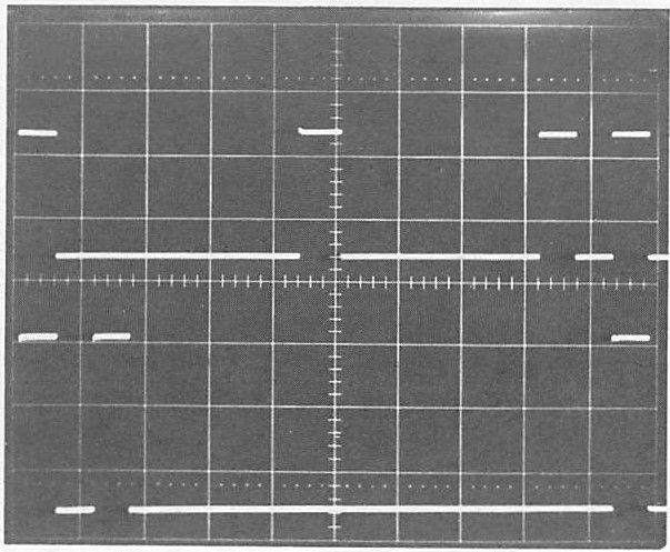
The delayed time base is started (or triggered) when the MTB sweep has reached a certain level, which is compared to a preset dc level. The preset level is thus reached a certain time after the MTB has started. This time is determined by the TIME/0 1v setting of the MTB. If the signal possesses a jitter, the display of the OTB will not be stable when operated in the START mode. Usually, selecting the TRIG mode of the OTB will eliminate this trouble.  If, however, the jitter is considerable, it can exceed the time between two adjacent waveforms. This may be the case with mechanical devices, such as tape or disk units of computer systems. Not even in the TRIG mode of the OTB can a unique display be obtained, because one delayed sweep may be triggered at waveform number 67 and the next one may be at waveform number 69. If all waveforms are identical (pulses), however, the display will be stable, although the observer will not know which pulse he or she is viewing.

Continue reading “The DTB with Digital Delay”