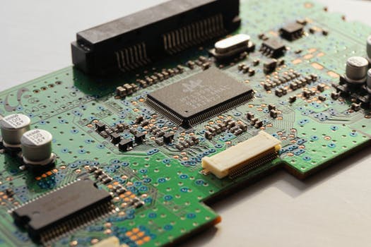
Digital Circuits

Input Networks and Amplifiers

The input network and amplifier perform the same functions as they do for the electronic analog meter. The input network presents a high resistance (11 megohms) to the circuit under test to keep from loading it down; it also attenuates the input voltage with the range switch setting to keep the test signal at the input of the amplifier under 1 volt. Although identical input and amplifier circuits can be used for both digital and analog meters, the example we are using demonstrates the use of an amplifier that can take up to 1 volt of input, and the ranges vary from 2 volts to 2000 volts, in multiplier ranges of 2, 20, 200, and 2000 volts. Since digital measurements use ten digits (0- 9), the counters, and especially the pulse generators deal in multiples of ten for convenience. The follower and amplifier circuits are both op-amps connected to accomplish their functions.

Continue reading “Digital Circuits”

Resistance Testing: Part 2

Circuit Tracing

As explained in the previous blog post “Resistance Testing: Part 1,” because of long lines, and because long lines can be buried or otherwise hidden from view, it is difficult to perform some tests without knowing which wires or connections are part of which circuits. A unique tracing system, which is available to quickly identify those parts on the same circuit, uses a hand-held radio transmitter and receiver to trace a circuit with radio-frequency signals. The transmitter can either be plugged into an outlet or connected anywhere in a line with alligator clips. The transmitter sends the signal along the lines to all other lines and components connected to it. The portable, hand-held receiver, which has a pickup antenna, is moved along the suspected path, whether the wires are in walls or buried, and the receiver will give an indication in the form of a light and a beeping tone when it is aimed at all the associated wires, outlets, switches, junction boxes, circuit breakers, etc.


Continue reading “Resistance Testing: Part 2”

Electromagnetic Meter Construction

Permanent Magnets

The moving-coil meter movement uses a horseshoe-shaped permanent magnet. The moving coil is placed within the magnetic field between the magnet’s two poles. However, if a simple horseshoe magnet were used, many of the magnetic lines of force would not cut through the moving coil. Magnetic lines of force travel the path of least resistance. Soft iron offers less resistance to lines of force than air. Therefore, soft iron pole pieces are attached to the poles of the magnet to concentrate the lines of force between the magnetic poles.

Continue reading “Electromagnetic Meter Construction”

Voltage Tests

Where there is an option for the types of tests or measurements that can be done, opt for the resistance check, which allows for all power to be “off. ” To play it safe in these instances, wherever possible, throw the mainline switch or associated circuit breaker off. Lock the switch off if possible or tag it. Wear clothing that covers as much of your body as possible to reduce the chances of inadvertent contact with “hot” points. Try to use one hand at a time to make connections. Wear rubber or plastic soled shoes that do not use nails and are not worn or frayed. Wear gloves for as many tests as possible and use tools that have insulated handles and test leads that are not frayed. When wiring must be disconnected for a voltage or current test, always disconnect the power before the wiring is disconnected or reconnected and discharge all capacitors.

Continue reading “Voltage Tests”

Electromagnetic Current Meters

How Current Affects a Magnetic Field

Current flowing through a coil produces the magnetic field that surrounds the coil. The strength of the magnetic field is proportional to the amount of current flowing through the coil. As the current increases, the strength of the magnetic field increases, and as the current decreases, the strength of the magnetic field decreases. For example, if the current through a certain coil is increased from 1 to 1.6 amperes, the magnetic field around the coil will be stronger for 1.6 amperes than it was for 1 ampere.

Continue reading “Electromagnetic Current Meters”