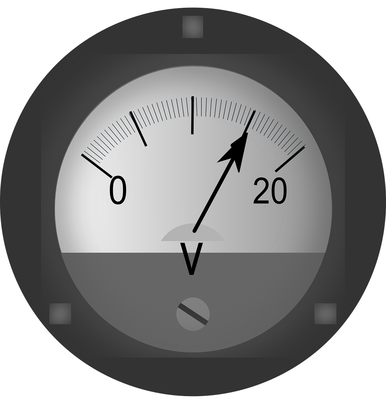
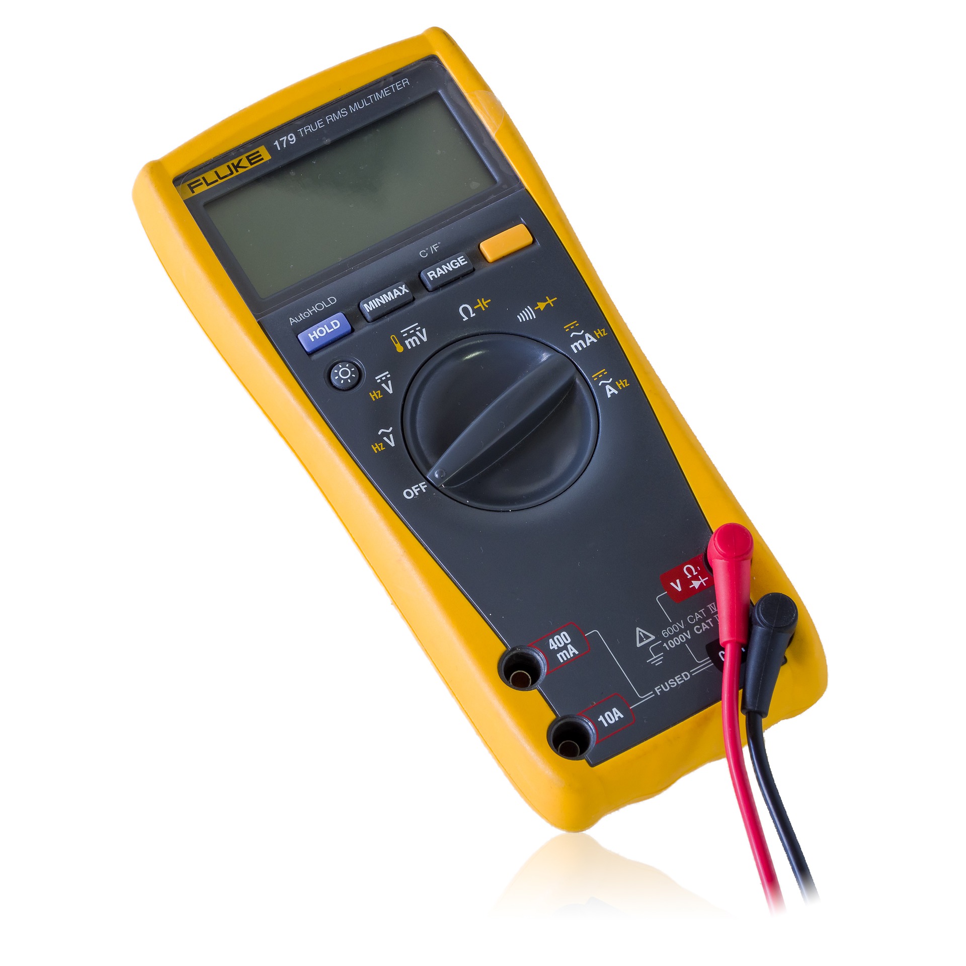
The electronic meter is used for resistance measurements in a manner similar to the way it is used for current measurements. Using the same types of amplifier stages as was used for the voltmeters and ammeters, where a 0.5-volt-signal produced a full-scale deflection, resistance circuits can be set up using standard battery source voltages supplying current to standard high precision resistance circuits, whose values are known. When the resistor under test is connected into the circuit, it will change the total resistance, resulting in a change in current flow, which produces a signal voltage that is directly related to the resistance under test.

Amplified ohmmeters can use series resistance or shunt resistance circuits. Here they will be explained in relation to the input signal voltage to the amplifier circuits.
Imagine there is a series electronic ohmmeter with a 1.5-volt battery to supply voltage to the ohmmeter input circuit. The input circuit contains test leads, a range switch, and precision known resistances. In addition, a zero-adjustment control is in the circuit to calibrate the zero reading whenever the meter is used. To completely calibrate the ohmmeter, first, the mechanical screw adjustment on the face of the meter movement is set to read infinite ohms. Then, the test leads are shorted together to swing the pointer toward zero, and the zero adjustment is set for the pointer to be exactly at zero. Essentially, zero is full-scale deflection, which with these amplifiers, puts about 0.5 volts at the input to the first op-amp. Since the battery is 1.5 volts, the zero-adjustment potentiometer value must be 100 ohms in the R x 1 range, 1000 ohms in the R x 10 range, and 100,000 ohms in the R x 1000 range. A 0- to 100,000-ohm potentiometer can be used.
When an unknown resistance is put between the test leads, since it is in series with the other resistors, the overall increase in resistance reduces the current flow and the signal voltage at the input of the first op-amp. Then, the meter pointer reads less than full scale. If the range switch is in the right setting, the pointer position is analogous to the value of the unknown resistance. The meter scale is calibrated in ohms, so the pointer shows the value of the unknown resistance.
With the series ohmmeter, the scale for the low resistance readings is crowded and difficult to read accurately. The shunt ohmmeter scale is less crowded for low resistance readings because full-scale readings occur oppositely for the series and shunt meters. With the series ohmmeter, low test resistances cause higher input signal levels and a zero ohms test, (shorted test prods) causes maximum signal level for full-scale deflection.

With the shunt ohmmeter, the test resistance is in parallel with the precision resistors, and their total shunt resistance goes down, causing a lower voltage signal level. Thus, an open test leads test, or infinite resistance causes the highest voltage level for full-scale deflection, and a shorted test leads test causes a zero-volt input signal for no deflection- the opposite of series ohmmeters. The smaller the test resistor, the smaller the deflection, so the meter scale can be calibrated in ohms. Since zero ohms causes no deflection, the screw adjustment on the face of the meter is set to put the pointer at zero, and the adjustment potentiometer is set for an infinity reading. The shunt ohmmeter requires much less adjustment than the series ohmmeter.
Sources:
https://www.seaward.com/gb/support/resistance/faqs/59780-a-guide-to-resistance-measurement


