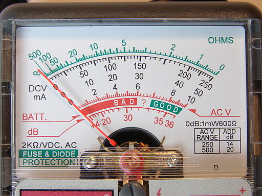
All electromagnetic current meters function on the basis that the intensity of the magnetic field around a coil is proportional to the amount of current flowing through it. Whether the meter you are using is alternating current (AC) or direct current (DC), knowing what to expect from the different meter movements is essential for correct calibration and accurate measurements.

Which Meters Are Used for DC and AC?
Basic meter movements include:
Moving-coil. This form of meter movement is used in almost all DC measurements, as it is the most accurate and sensitive.
Rectifier-type moving-coil. It is not possible to use a moving-coil meter to directly measure AC. Therefore, a rectifier must be added to moving-coil meter movement to convert AC to DC. This is the most common meter for measuring AC.
Iron-vane. Measures both DC and AC (typically used for measuring low-frequency AC).
Thermocouple. Measures both DC and AC. Because it is the only meter capable of measuring these high frequencies, it is almost solely used to measure radio frequency (RF) currents.
The Calibration Process
The calibration process of both dc and ac meters is roughly the same. For a DC meter to be calibrated, it must be linked to an extremely accurate dc current source. The current source’s output must be changeable, and some method of monitoring the source’s output current must be accessible. For this purpose, several sources feature a built-in meter. The current source’s output is adjusted in very small stages, and the scale of the calibrated meter is marked to match the reading on the monitoring device with each step. This method is repeated until the meter’s full scale has been calibrated.
This same calibration technique is used for an AC meter. The difference is that a 60-Hz sine wave is primarily used. An AC meter measures the average value of a sine wave, but it is preferable for the meter to display effective or rms values. As a result, the scale’s equivalents are calculated and noted.
Thermocouple meters are calibrated using a sine wave, but at the frequency that the meter will be used. The current in a wire moves closer to the wire’s surface at certain frequencies- the higher the frequency, the closer to the service. When used at extremely high frequencies, this is known as the “skin effect”. Because the diameter of the thermocouple heater wire shrinks as a result of this process, the resistance of the wire rises. As a result, thermocouple meters must be calibrated at specified frequencies, generally in the kilohertz or megahertz ranges.
Meter Accuracy
The accuracy of moving-coil meters designed for common usage is around 2%. Moving-coil meters designed for laboratory usage or other particular purposes, on the other hand, often have an accuracy range of ±0.1 to ±0.5 percent (±1/10 to ±1/2 of 1 percent). Keep in mind that meter accuracy is dependent on full-scale deflection. The accuracy of moving-iron meters, including concentric-vane and radial vane types, is around ±5%. Although a rectifier meter is essentially a moving-coil meter, it lacks the precision of a conventional moving-coil meter. The inaccuracy of the meter movement is compounded by the inaccuracy of the rectifier, and the total accuracy of the meter is frequently less than ±5%.
Frequency Response
The inductive reactance of the coil limits the frequency response of a moving-coil or moving-iron meter. The equation for calculating a coil’s inductive reactance (XL) is:
XL = 2πfL
Where f is the frequency and L is the coil’s inductance. For moving-iron meters, they can be used up to roughly 100 Hz without significantly increasing meter error. Readings become unreliable above this frequency. The frequency response of moving-coil meters is a bit better.
The capacitance present across the rectifier is what limits the frequency of the rectifier-type meter. For example, while the capacitive reactance of certain rectifiers grows, the capacitive reactance of others decreases, as shown by the equation:
XC = 1 / 2πfC
Across the rectifier, it operates as a low-resistance AC path. For every 1,000 Hz increase in frequency, meter readings drop by around 0.5% to 1%.
Source:
Mileaf, Harry. “Meter Calibration and Accuracy.” Electrical Test Equipment, H.W. Sams, Indianapolis, Ind, USA : 1989.
Additional Information:
https://www.meracalculator.com/physics/electromagnetism/capacitive-reactance.php
http://www.learningaboutelectronics.com/Articles/Inductive-reactance


