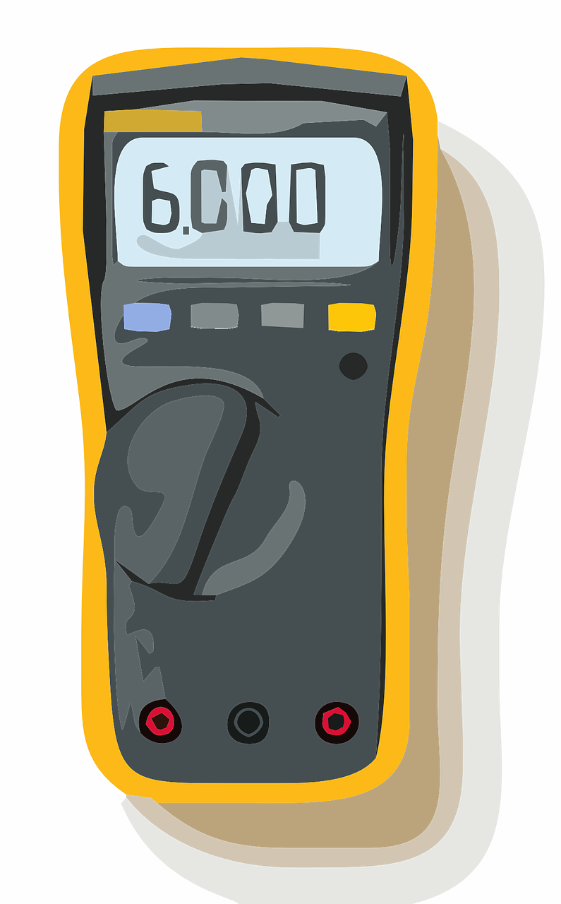
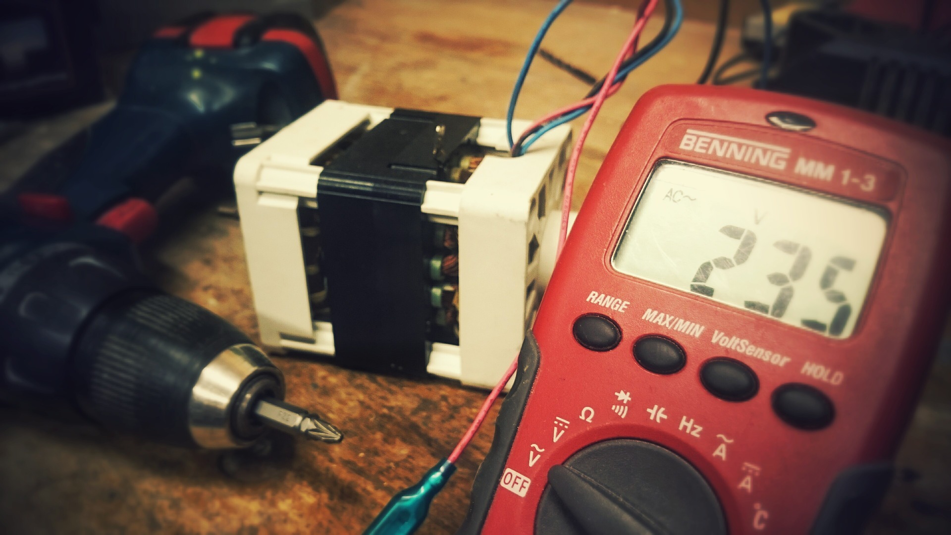
Current-measuring meters are called ammeters. There are two ways of measuring the current flowing in a circuit. The first way is to open the circuit being tested and link the meter test leads into the circuit so the current flowing in the circuit flows in series through the meter as well. This is the in-circuit-type of ammeter sometimes referred to as an in-line meter. An external type of ammeter, known as a clamp-on ammeter, can be used without opening the circuit. The clamp-on ammeter has jaws that open and clamp around the sides of one wire in the circuit and measures the magnetic field that the current in the wire produces, to determine the current flow. The clamp-on ammeter is widely used and simplifies the measurement of current from one to hundreds of amperes. It is especially helpful for field testing and troubleshooting AC power lines.
Current meters must always be connected in series with the power source and the load, and never connected in parallel with them. The only exception is for a clamp-on meter. A current meter is a low-resistance device. Most circuit components have a much higher resistance. If you connect a current meter in parallel with one of these components, you might create a short circuit, resulting in high current flow through the meter. With an analog meter that does not have built-in amplifiers, this high current will damage or ruin the meter movement. If you utilize a multirange current meter, the meter movement or circuits, or both could be damaged by excess current. With electronic meters, both analog and digital, which have built-in amplifier circuits, the input circuits of these meters could be burnt out. The better meters have fuses in the ammeter input lines to protect the meters. Thus, it is important to always connect a current meter in series with the power source and load.

A second important point to remember with analog meters is to observe polarity when measuring current in a DC circuit. You must connect the negative terminal of the meter to the negative, or low potential point in the circuit, and connect the positive terminal of the meter to the positive, or high potential point in the circuit. Current must flow through the meter from minus (-) to plus (+). If you connect the meter so that the polarities oppose, the meter coil will move in the opposite direction, and the pointer might strike the left retaining pin. You will not obtain a current reading, and in some cases, the pointer might be bent.
With digital meters, reverse polarity is not a problem. If the leads are hooked up in reverse, the digital reading will be preceded by a minus sign, signifying a reverse current.
You do not have to observe polarities with analog meters that have the zero position at the center of the scale. With AC current, you don’t have to observe polarity since the polarity is continually changing through the cycles. Therefore, meters created solely for AC use do not have polarities marked at their terminals.
A third important point to remember with an analog meter is to not connect the meter into a circuit unless you know the estimated current flowing in the circuit. Analog meters are frequently damaged or ruined when they handle currents higher than their ratings. If you are not sure how much current is flowing, check the diagrams, and begin by connecting a meter with a range higher than required. If a multirange meter is utilized, set it to its highest scale, and reduce the range until you reach the range that gives a good reading. It should be as close to full-scale deflection as possible for the highest precision. If you begin with the lowest range, the pointer could strike the right retaining pin at the high end of the scale.
Many electronic digital meters have a special autoranging feature, where the meter automatically sets itself to the proper range to match the current being tested.

Sources:
https://courses.lumenlearning.com/boundless-physics/chapter/voltmeters-and-ammeters/
https://www.allaboutcircuits.com/textbook/experiments/chpt-2/ammeter-usage/
https://www.electronics-notes.com/articles/test-methods/meters/how-to-measure-current.php


