Input circuits allow the input voltage to be stepped down by the ranging circuits, which could be a switch or automatic circuits. The ranging circuits also select the proper pulse stream from the clock and divider circuits. The test voltage is amplified and integrated with the gate pulse to produce a ramp voltage that will pass a selected sample of pulses. The number of pulses passed is related to the test voltage. These are shaped and counted, and then decoded to drive the seven-segment displays.
Just as with analog electronic ammeters, the digital amplifier circuits are voltage sensitive. This means that the same basic amplifier circuits that are used for voltage measurements can be used for current measurements if the current being tested is converted to a corresponding voltage following Ohm’s law. When the meter is set up as an ammeter and is connected into the circuit, corresponding voltage drops will appear across the input circuit’s precision resistors. The proper pulse stream is selected from the clock or divider circuits so that when it is counted, the readout will be in amperes to correspond with the signal voltage processed.
As with the ammeter circuits, the ohmmeter function uses its own input circuit to create a corresponding test voltage that can be processed by the same digital meter stages. The resistance being tested will control the current flow in the input circuit, which will develop a related signal voltage. Again, the proper pulse stream is used so the pulse count will produce digits that represent the ohms reading, even though the signal is a voltage.
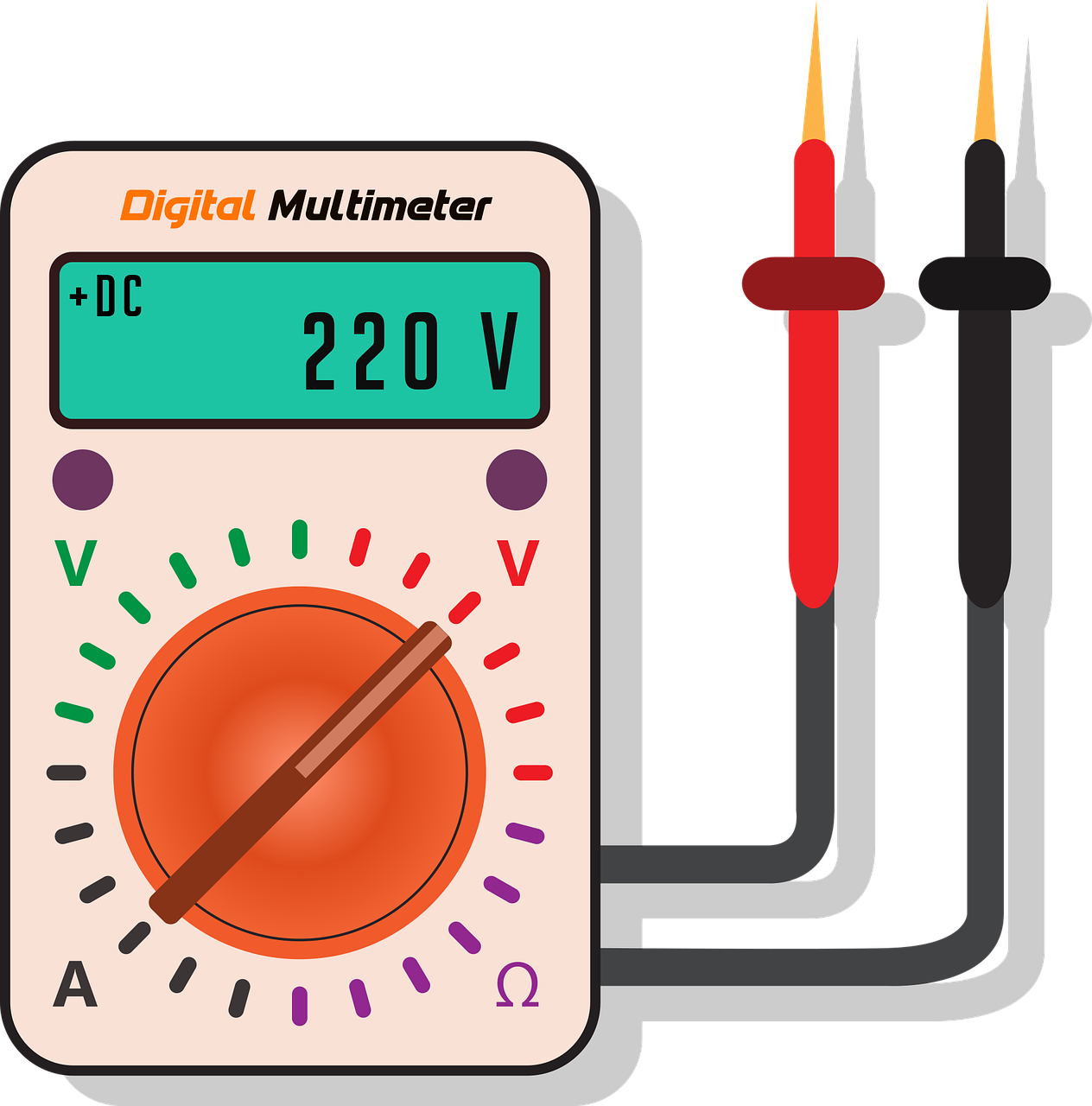
Since the same basic stages can be used to process a test voltage that can represent voltage, current, and resistance, the system can combine the three input circuits to create a multimeter. The function switch is set for the desired function, and to the specific range (unless it is an autorange meter). The test leads are connected to their specific jacks, and the COM (mon) jack is used for all tests, in this case.
With some other meters, different sets of jacks are used for each test. This meter has a continuity setting, which is a low or zero-ohms resistance test that also sounds a beeper to indicate continuity. The ac/dc slide switch is set for either ac or dc. In addition to the digital readout, some meters have an analog bar graph below the digits to show the reading in a horizontal bar graph with tic marks, which is similar to some analog scales. The analog bar graph works a little faster than the digital readout. The analog reading must be multiplied by the range setting, just as with the analog meters.
Sources:
https://www.sciencedirect.com/topics/engineering/digital-meter


