“Cut the red wire!” This is a familiar line to any fan of high-stakes action movies like Lethal Weapon. In the movies, characters hoping to diffuse a bomb before it’s too late are faced with a dilemma- what color wire do they cut? While the answer to that question may depend on the film- the difference in color coded wires has real life consequences. How does a color coded system improve electrical safety? Are all color coding systems still used today? Most importantly- what do all of these different colors mean?
Wiring Color Codes
Electrical wires are everywhere. In power circuitry, color coded wires take the guesswork out of how power is moving throughout the circuits, resulting in more efficient performance. Knowing how to handle the specific colors also reduces the chance of electrical burns or shock, and helps prevent cutting the wrong wire (which can result in costly repairs or replacements!).
The standard for color coding depends on the country or region that you are in.
Europe & the UK
Color Standards for AC Power Circuit Wires
The International Electrotechnical Commission (IEC) dictates the coloring codes for AC branch circuits throughout most of Europe. While the UK is not a part of the European Union following “Brexit” in January 2020, they still abide by the same IEC AC color codes.
The specific wire functions (with their labels in parentheses) and their corresponding colors are as follows:
● Protective Earth (PE): green-yellow (the hyphen between the two colors indicates that it is a green wire with a yellow stripe).
● Neutral (N): blue
● Single Phase Line (L): brown
● 3 Phase Line (L1): brown
● 3 Phase Line (L2): brown
● 3 Phase Line (L3): gray
Color Standards for DC Power Circuit Wires
● Protective Earth (PE): green-yellow
● 2-Wire Unearthed DC Power System
○ Positive (L+): brown
○ Negative (L-): gray
● 2-Wire Earthed DC Power System
○ Positive [of a negative earthed circuit] (L+): brown
○ Negative [of a negative earthed circuit] (M): blue
○ Positive [of a positive earthed circuit] (M): blue
○ Negative [of a positive earthed circuit] (L-)” gray
● 3-Wire Earthed DC Power System
○ Positive (L+): brown
○ Mid-wire (M): blue
○ Negative (L-): gray
The USA
Color Standards for AC Power Circuit Wires
Color code standards for AC power circuits in the US are dictated by the US National Electrical Code (NEC).
● Protective Ground (PG): bare, green, or green–yellow
● Neutral (N): white
● Single Phase Line (L): black or red (2nd hot)
● 3 Phase Line (L1): black
● 3 Phase Line (L2): red
● 3 Phase Line (L3): blue
Color Standards for DC Power Circuit Wires
● Protective Ground (PG): bare, green, or green–yellow
● 2-Wire Ungrounded DC Power System
○ Positive (L+): red (no recommendation)
○ Negative (L-): black (no recommendation)
● 2-Wire Grounded DC Power System
○ Positive [of a negative grounded circuit] (L+): red
○ Negative [of a negative grounded circuit] (M): white
○ Positive [of a positive grounded circuit] (M): white
○ Negative [of a positive grounded circuit] (L-)” black
● 3-Wire Grounded DC Power System
○ Positive (L+): red
○ Mid-wire (M): white
○ Negative (L-): black
Canada
The Canadian Electric Code (CEC) decides the AC power circuit color codes throughout Canada. They are very similar to the USA.
Color Standards for AC Power Circuit Wires
● Protective Ground (PG): green or green-yellow
● Neutral (N): white
● Single Phase Line (L): black or red (2nd hot)
● 3 Phase Line (L1): red
● 3 Phase Line (L2): black
● 3 Phase Line (L3): blue
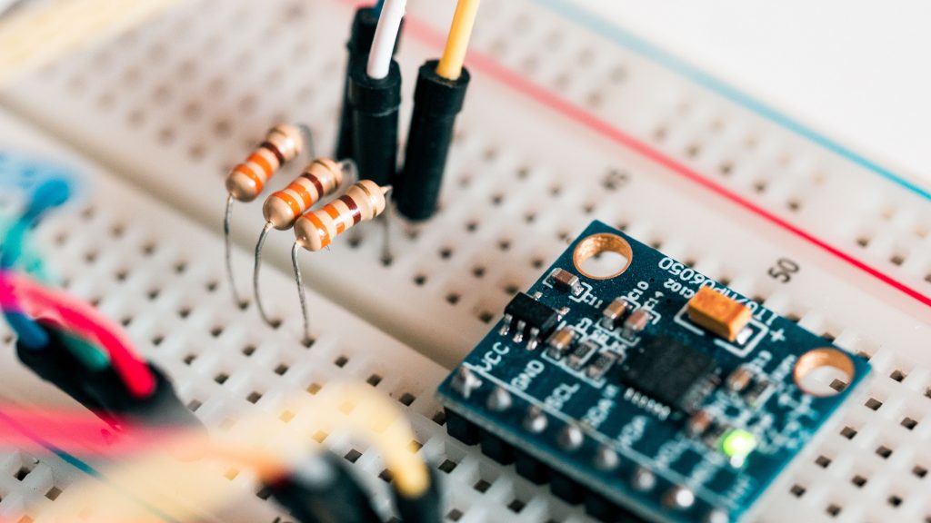
Resistor Color Codes
In the 1920s, the electronic color code was developed by the Radio Manufacturers Association, which is now a division of the Electronic Industries Alliance (EIA). This color coding system was created by using a series of colored bands, which were easy to print on small electronic components such as resistors. These colors helped engineers and electricians easily identify the value and function of a component.
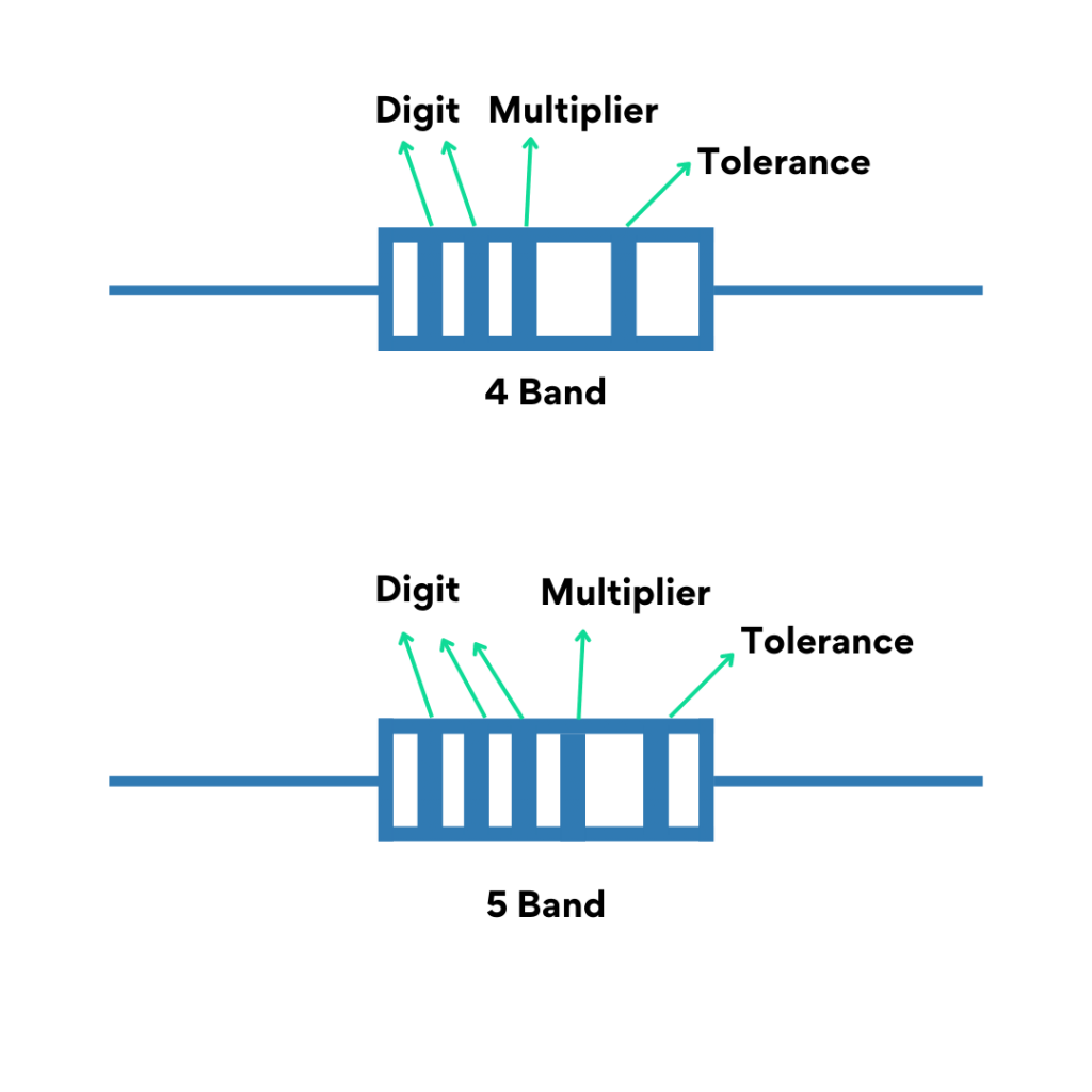
It can sometimes be difficult to figure out the orientation of the colored bands. For this reason, there is more distance between the 3rd and 4th bands to indicate the direction in which it should be read.
The last band on the resistor is the tolerance, and are often either gold or silver. When in doubt, consult the manufacturer’s documentation.
Color-coded resistors come in either 5-band or 4-band variations, with 4-band resistors being the most common. Green, red, violet, and blue can be used as tolerance codes, but only on 5-band resistors, since they use colors for the tolerance band.
The color band system did present some challenges, especially for those who were colorblind. The difference between colors such as red, brown, or orange could be hard to tell if there was debris or if the component had been overheating. One benefit of the color band system is that a colored band all the way around the component could be seen no matter how the component was turned. In modern times, the E-series of values is used to imprint a code on the part instead of using colors.
Additional Information:
https://iec.ch/homepage
https://esfi.org/workplace-safety/industry-codes-regulations/the-national-electrical-code-nec/
https://www.csagroup.org/standards/areas-of-focus/electrical/
https://community.fs.com/blog/necessity-and-standards-of-electrical-wiring-color-codes.html


