This guide will cover how-to setup Site Master: Measurement Type, Frequency, Amplitude, Markers, Limit Line, and DTF.
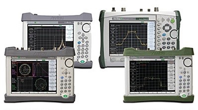
Anritsu’s handheld cable, antenna, and spectrum analyzer family, known as the Site Master series is designed for engineer’s in-field measurements.
This brief, basic guide will review some measurement setups involving the following models: S331E, S332E, S361E, and S362E.
Let’s begin.
Step 1: Power on the unit and push the Menu button and select one of the following via touchscreen. (These units have 8.5 inch TFT color displays).
- Cable-Antenna Analyzer
- Transmission Measurement
- Spectrum Analyzer
- Power Meter
- High Accuracy Power Meter
- Interface Analyzer
- Channel Scanner
- CW Signal Generator
Note: This menu screen may be different based on the installed options.
Step 2: Select your Measurement type by pushing the main menu button and choosing your measurement.
Step 3: Setting the Frequency: Push the Freq/Dist menu button, push Start Freq and enter the data then do the same for Stop Freq. Use the arrow keys, knob, and keypad.
Step 4: Setting the Amplitude: Push the Amplitude menu button, then the Top menu button and enter the data then do the same for Bottom. Use the arrow keys, knob, and keypad.
Step 5: Turning on your Markers: Push the Marker menu button and push the Marker 1 2 3 4 5 6 sub-menu keys – select #1 via the touch screen. Then, using your arrow keys, knob and keypad move the marker, note the selected marker is shown in the top left corner of the Site Master’s graph.
Note: Delta Markers are optional for all 6 markers – select the Delta On/Off sub-menu to turn on the Delta Markers.
Step 6: Peak/Valley Auto Markers: If you are measuring Return Loss & VSWR, you may want to use the Site Master’s Peak/Valley Auto features. These can automatically engage Marker 1 to peak, Marker 2 to valley. M1 & M2 will be displayed in the Marker Table. To set this up push Marker > Peak/Valley Auto on your Anritsu Site Master.
Step 7: Set up the Single Limit Line: Push Shift > Limit in order to view the Limit Menu. Then push Limit On/Off to set the Site Master Limit. Push Single Limit, adjust the limit value numeric keypad, and push Enter. Finally, push the Limit Alarm button to engage the alarm on or off.
Step 8: Setting up the DTF.
- Push Measurements’ main menu button and choose the DTF VSWR or DTF Return Loss button.
- Push Freq/Dist menu button.
- Select Units sub-menu button and choose m which shows the distance in meters OR ft which shows the distance in feet.
- Push DTF Aid to set the parameters using the touchscreen: set Start Distance and Stop Distance (which must be lower than Dmax).
- Enter the Site Master’s Start & Stop Frequencies.
- Then choose the correct cable by pushing Cable then Enter.
- Push Continue. Push Shift > Calibrate.
- Set the Markers, Limit Lines then File & save.
This concludes the basic setup guide of the Anritsu Site Master’s Measurement Type, Frequency, Amplitude, Markers, Limit Line, and DTF.
For calibration instructions, check our post “How to Calibrate Anritsu SiteMaster with OSL Calibration.”


