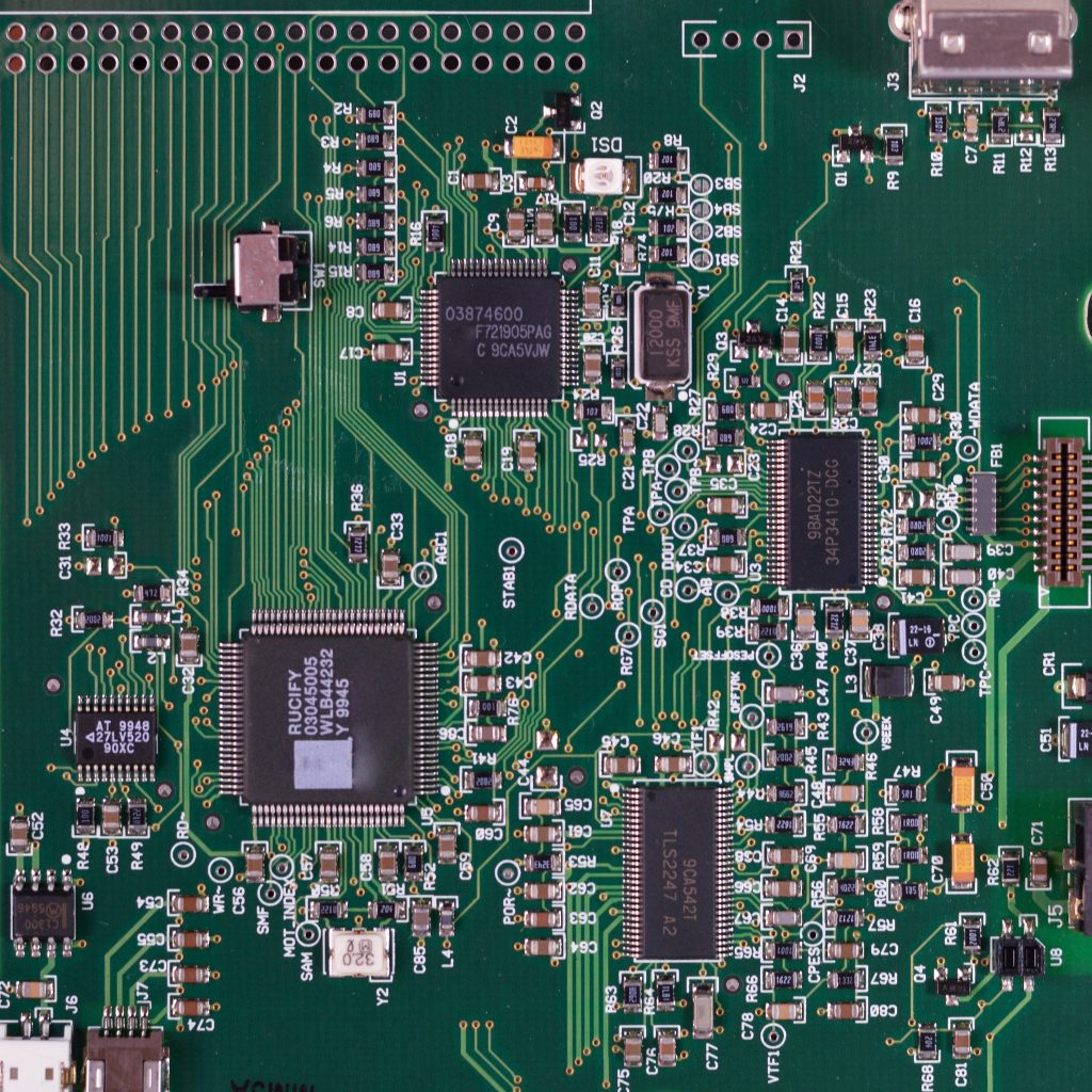
When it comes to verifying the functionality and performance of products during manufacturing, Automatic Test Equipment (ATE) is an irreplaceable tool. Two of the most prominent types of ATE used in product testing and field servicing are in-circuit and functional ATE. This article will take a look at how both of these types work, as well as the advantages and disadvantages of both.
In-Circuit ATE
In-circuit test fixtures use a “bed-of-nails” interface to test the individual components on an assembled printed circuit board (PCB) to determine their value and to identify any manufacturing defects. The board under test (BUT) is forced down on the bed-of-nails, which is so named because of the various spring loaded pins that resemble nails. These pins are maintained by a pneumatic or a vacuum force, and they can be arranged into a variety of patterns.
Both the passive and active values of the individual components of the PCB are sequentially measured in-circuit, and these values are checked against stored standards (or a software model of the PCB) to isolate faulty ones. Some faults that an in-circuit tester may identify include, but are not limited to; short circuits due to poor soldering/layout, incorrect wiring, missing components, incorrect orientation of components, faulty components, and open-circuited tracks.
Any faults discovered through the in-circuit testing are isolated and reported in a printout display. Depending on the number and type of components on the PCB, the entire process is completed within a few minutes.
How it Works:
Stimulus signals are routed to the appropriate test points on the board-under-test via the switching unit and the bed-of-nails interface fixture.
Responses are routed to the measuring device (which is controlled by the computer) from the interface fixture and the switching unit. Results are fed to the computer for calculation, comparison, and processing.
Test results can be recorded on a disc and printed out in a “‘repair ticket” that indicates the faulty components. By tabulating the frequency of fault incidences, potentially bigger problems such as possible faulty component batches, repeated assembly faults, or process errors can be addressed.
A good general-purpose in-circuit tester should have measurement capabilities, facilities that make it easy to change the bed-of-nails interface fixture, and the capability to directly program both program modification or program generation.
Advantages of In-Circuit Testing
– Low initial cost
– Easy to operate and program
– Incredibly effective when it comes to isolating production faults
Disadvantages of In-Circuit Testing
– An individual bed-of-nails fixture is required for each type of board to be tested, resulting in high interface costs.
– A vacuum or pneumatic power source is required for successful operation
– It does not test the dynamic performance of the components.

Functional ATE
A functional tester is used to assess the performance of the test board under typical working conditions. Functional testers use an edge connection to access the board-under-test, which simplifies and lowers the cost of interface connector design In comparison to the bed-of-nails fixture. Depending on the board’s architecture, extra connections could occasionally be required using chip probes or connectors.
The functional tester is able to quickly determine if the PCB is sound or faulty through the use of a basic Go/No-Go test. A No-Go result indicates the presence of hardware failure. This failure could be caused by a variety of things; faults in PCB manufacturing, faulty ICs, faulty IC pin connections, or faults in assembly.
The Go/No-Go test may pinpoint the fault’s location but it is often not accurate enough to allow for repairs. For greater accuracy, additional diagnostic tests must be performed to achieve this. These additional tests may involve monitoring and examining waveforms using a digitizing programmable oscilloscope, or by using a “roving probe” in the case of a digital board-under-test.
How it Works:
The functional tester utilizes an IEEE-488 instrumentation bus for interfacing the programmable instruments, and a peripheral bus for interfacing the peripherals to the microprocessor-based controller. Two memory stores are used: a permanent ROM store for the master program containing the basic programming requirements, and a RAM chip that stores the program dedicated for the particular board to be tested.
The stimulus signals of the test are produced by the pulse of the signal generator under the direction of the controller, and they are then fed into the board under test via an edge connector interface. Output responses are picked up from the edge connector of the board and routed to one or more of the measuring devices via the interface.
The controller receives the measured results, compares them with those expected from a good board, and indicates the results. Further detailed tests to identify the precise fault may be carried out manually, either under the control of the operator using the keyboard or under instructions from the tester by directing the operator to the steps to be taken.
Advantages of Functional Testing
– Has a very high fault coverage (around 90 – 98%) due to it verifying the actual operating specification of the board-under-test.
– Significantly faster than in-circuit testing because not every component has to be tested individually.
– Edge connection is simple to design and cheap to make.
Disadvantages of Functional Testing
– Expensive
– More complex to program
– Isolating the fault in a faulty board is difficult and time-consuming.
Additional Information:


