Measurements of electrical voltage are used to determine the possible differences in electric charge between two different points in an electric circuit. This data makes it possible to ascertain how much power is being used by a specific object, compared to how much power is available in the circuit. Since it allows us to ensure that an electrical circuit is operating both correctly and safely, this information is essential for the design, installation, and operation of electrical systems.
Safety First!
Electrical safety is the crucial first step to any voltage test. Electrical shocks can be deadly, even in everyday household circuit situations. None of the voltage testing methods listed below should be taken lightly, but should be used with caution after taking appropriate safety steps. Whenever possible, the best type of check to use is a resistance check, since it allows for all of the power from the mainline switch / any associated circuit breaker to be switched off prior to testing. If possible, it is good practice to lock the switch into the off position.
Clothing is also an important consideration before engaging in any form of electrical measuring / testing. You will want to choose clothes that cover as much of your body as possible to lessen the chance of accidental contact with a “hot” point. (A “hot” wire indicates one that has a live electrical current). Shoes with rubber or plastic soles are ideal, as well as thick gloves. Tools should have insulated handles, and test leads should not be frayed. If it is necessary to disconnect wiring, make sure that that power is disconnected before disconnecting or reconnecting any wiring, and that all capacitors are discharged.
Some environments do not meet the standards of the National Electrical Code. These situations include any kind of wet environment, a location with metal / fiber / grain dust, or a location with the presence of gaseous vapors or fuels. Extreme caution under direct expert supervision should be exercised in these types of environments.
Neon Bulb Testers
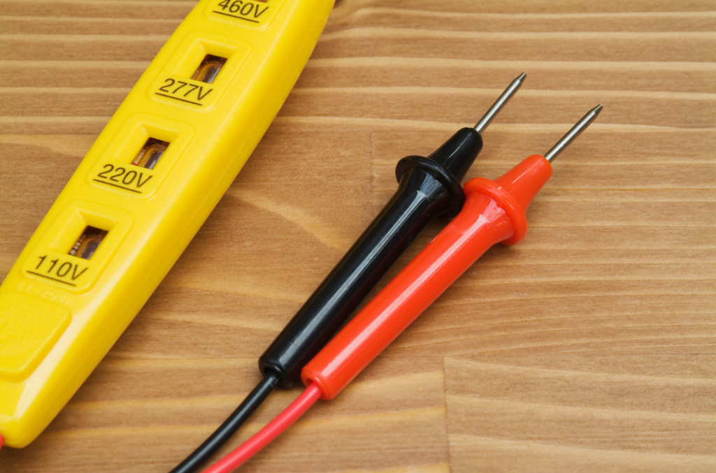
The neon tester is a simple, inexpensive meter device that makes it easy to quickly check and see if an outlet is “hot” or not. The bulb of the neon tester will glow when it comes into contact with both a hot line and ground terminals- it will not light up when connected between grounded terminals. In general, these testers will not light up for voltage less than 80 volts, and can be used to safely identify voltages up to 250 volts (though upper limits / ratings may vary depending on the specific tester). There are 2 elements in the neon tester- detection of a dc voltage causes one element to glow, while an ac voltage causes both elements to glow. Similar to the neon tester, a plug-in tester that utilizes 3 glow lamps and a combination of 6 lights can also be used.
Solenoid Testers
While not quite as accurate as a digital or analog meter, the readings from the solenoid tester are useful in applications for power lines. Another simplistic testing device, the solenoid tester provides more information than the neon bulb tester via a straightforward colored line indicator. When this tester comes in contact with voltage, an electromagnetic current flows through it and draws in an iron core. The higher the level of voltage, the farther the core goes in. This movement is reflected on the color bar / indicator line of the device, showing scale readings for either AC or DC. The red and black test probes used by the solenoid tester have corresponding indicators- showing either black or red depending on which probe has connected to a positive DC potential.
Testing Junction Boxes
Say your analog or digital meter indicated low voltage in the outlet or power connection point where it was used to measure. What is the next step? In this scenario, the circuit voltage of the junction box at the main entrance of the home / building can be tested to see if there is a reduced power level being supplied, if there is a high resistance connection, or if the issue occurs somewhere else along the associated line. If the outlet routing / wiring is unfamiliar, the circuits can be traced by switching the circuit breakers on and off and seeing what is affected.
Testing Thermostat Voltage
Thermostats usually come in two types, depending on the heating and / or cooling system used. High-voltage thermostats control equipment by using voltage directly from the power line. Low-voltage thermostats are more commonplace in homes and small commercial locations, and use a transformer within the power line to reduce the voltage to a safer level (24 volts DC). This means that the low-voltage thermostat utilizes a 24 volt relay, while high-voltage thermostats have more direct control. To measure the voltage of a low-voltage thermostat, an AC or DC meter should be used directly on the thermostat wire (in the thermostat mounting bracket) for the most accurate reading.
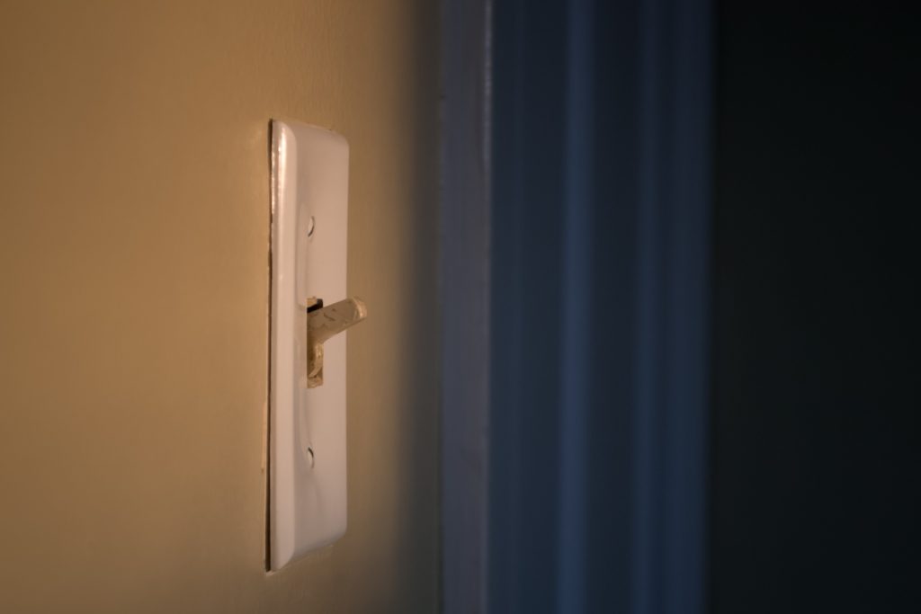
Testing Power Switch Voltage
Power switches are usually connected to the ground side of a power line to either block the line of voltage to the equipment or to let it pass- turning the circuits either off or on. A meter should only display a voltage reading when the switch is in the “off” position. This is because when a switch is in the “on” position, the contacts are connected as though it were a singular wire- leading to a voltmeter reading of “0”. When a switch is in the “off” position, the voltage should be able to be read by the meter across the open switch. If a meter reads a line voltage when the switch is in the on position, there is an issue with the switch remaining open. The aforementioned neon tester is a helpful tool in this testing scenario.
Additional Information:
Source:
Mileaf, Harry. Electrical Test Equipment, H.W. Sams, Indianapolis, Ind, USA : 1989, pp. 29–35.


