1 + 1 = 1. While this statement would be false when discussing the real numbers of ordinary algebraic concepts, It makes perfect sense in the context of Boolean Algebra. This mathematical concept is most practically applied when simplifying logic circuits. When the function of a logic circuit can be translated into Boolean form, then the resulting equation can be simplified by applying certain algebraic rules- allowing a circuit with fewer components to perform the same function.
The Basics of Boolean
While it is often confused with binary notation due to the exclusive use of the ciphers 1 and 0, Boolean numbers constitute an entire mathematical system distinct from real numbers. By contrast, binary is simply another way to notate real numbers, and the different bits can be added together in order to equal a value that is any (finite) size. Boolean numbers are limited to two possible values: either true (1) or false (0).
Boolean addition is equivalent to the logical operation of an “OR” gate. When adding Boolean numbers together, consider the following diagrams:
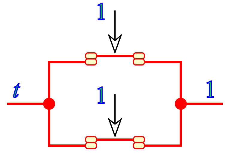
This set of parallel switch contacts demonstrates that 1 + 1 = 1 (true)
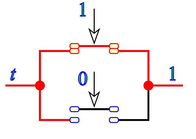
While the bottom switch is disconnected, resulting in a 0 (false), the top switch is still connected and results in a 1 (true). This demonstrates that 1 + 0 = 1.
While Boolean addition is equal to the “OR” logic function / parallel switches, Boolean multiplication is equal to the “AND” logic function / series switches. As the name suggests, the difference between series and parallel switch contacts is that series switches are linear, as opposed to being on opposite sides. Boolean multiplication operates under the same rules as “regular” algebra, where anything that is multiplied by 0 equals 0, while everything multiplied by 1 does not change.
While Boolean algebra is similar to real number algebra in the way that it employs alphabetical letters to represent variables, Boolean variables are always capitalized. There is a complement for every variable. The complement is the opposite of its value since they can only have one of two potential values. For instance, if variable “A” is equal to 0, its complement will be equal to 1. In Boolean notation, complementation is indicated by a bar placed above the variable character, like Ā.
The basic properties of Boolean algebra are:
Commutative properties, which are applied equally to both addition and multiplication.
• In Addition: A + B = B + A
• In Multiplication: AB = BA
Associative properties, which are also applied equally to both addition and multiplication and “associate” groups in parentheses without changing the equation’s truth.
• In Addition: A + (B + C) = (A + B) + C
• In Multiplication: A(BC) = (AB)C
The Distributive property, which shows how to extend a Boolean expression generated by the product of a sum.
• A(B + C) = AB + AC
Circuit Simplification
There are three Boolean rules that are useful for simplification. These are listed below, as well as the steps taken to symbolically prove them.
A + AB = A
Start with A + AB
Factor out A:
A(1 + B)
Apply A + 1 = 1:
A(1)
Apply 1A = A as the final step:
A
A + ĀB = A + B
Start with
A + ĀB
Apply A + AB = A:
A + AB + ĀB
Factor out B:
A + B (A + Ā)
Apply A + Ā = 1:
A + B(1)
Apply 1A = A for your final step:
A + B
(A + B) (A + C) = A + BC
Start with (A + B) (A + C)
Distribute:
AA + AC + AB + BC
Apply AA = A:
A + AC + AB + BC
Apply A + AB = A to A + AC:
A + AB + BC
Apply A + AB = A to A + AB as your final step:
A + BC
To convert a gate circuit for a semiconductor into a Boolean expression, first label each gate output with a Boolean subexpression that matches the gate’s input signals. Once you are finished labeling all of them, write the final expression at the end. If you’re converting from an expression to a gate circuit, start by evaluating it using the conventional sequence of operations. This means that multiplication is done before addition, and operations within parentheses are done before anything else.
When converting an electromechanical ladder logic circuit into a Boolean expression, first label each rung of the circuit with a Boolean sub-expression that matches the input signals of the contacts until a final expression is achieved at the last coil or light. Treat the connections as if they were resistors, and as if you were calculating the overall resistance of the series-parallel network they created in order to establish the right evaluation order. To put it another way, start by looking for contacts that are immediately parallel or series with one another, and then “collapse” those contacts into comparable Boolean sub-expressions before moving on to additional contacts.
Additional Information:


