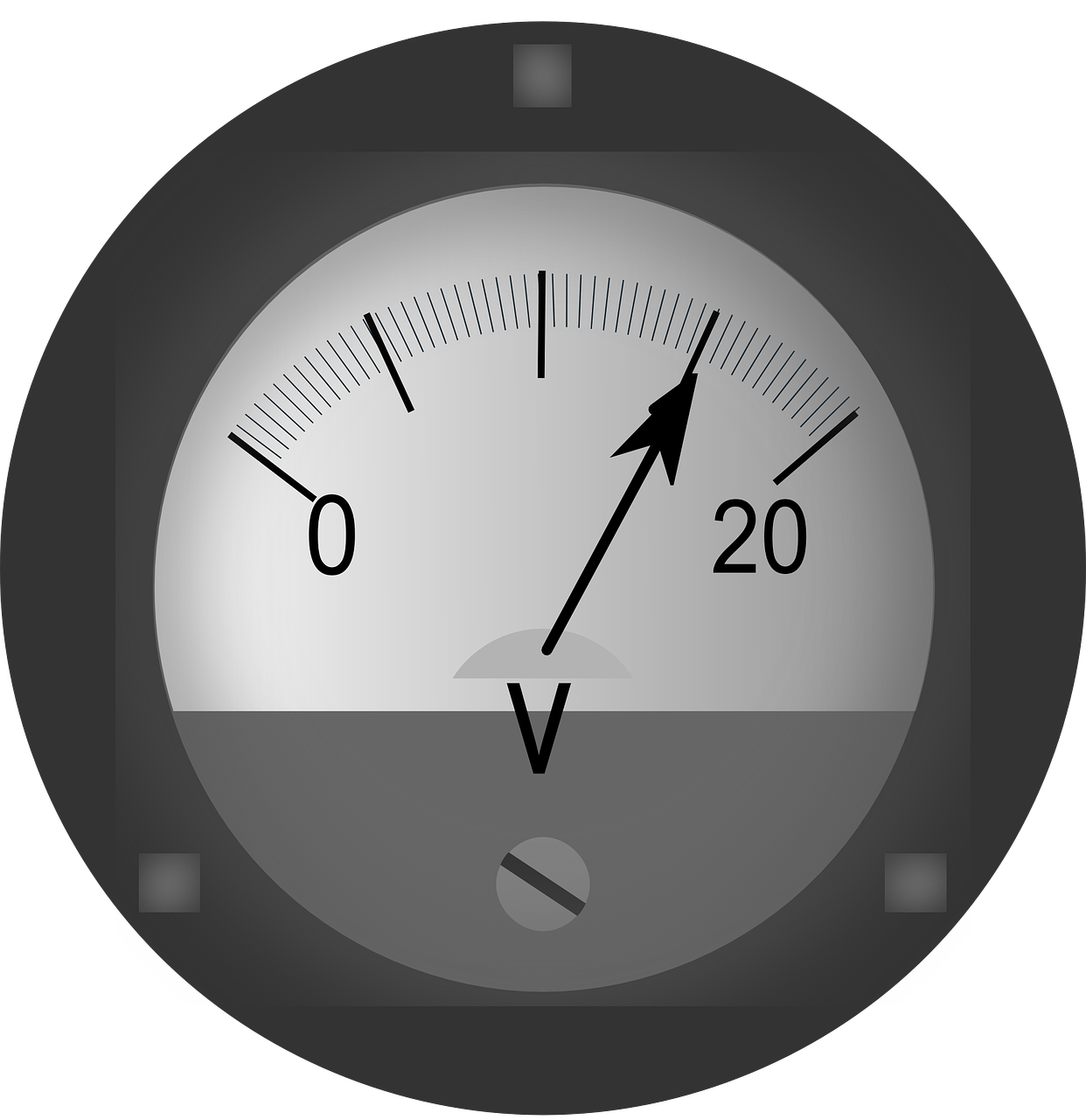
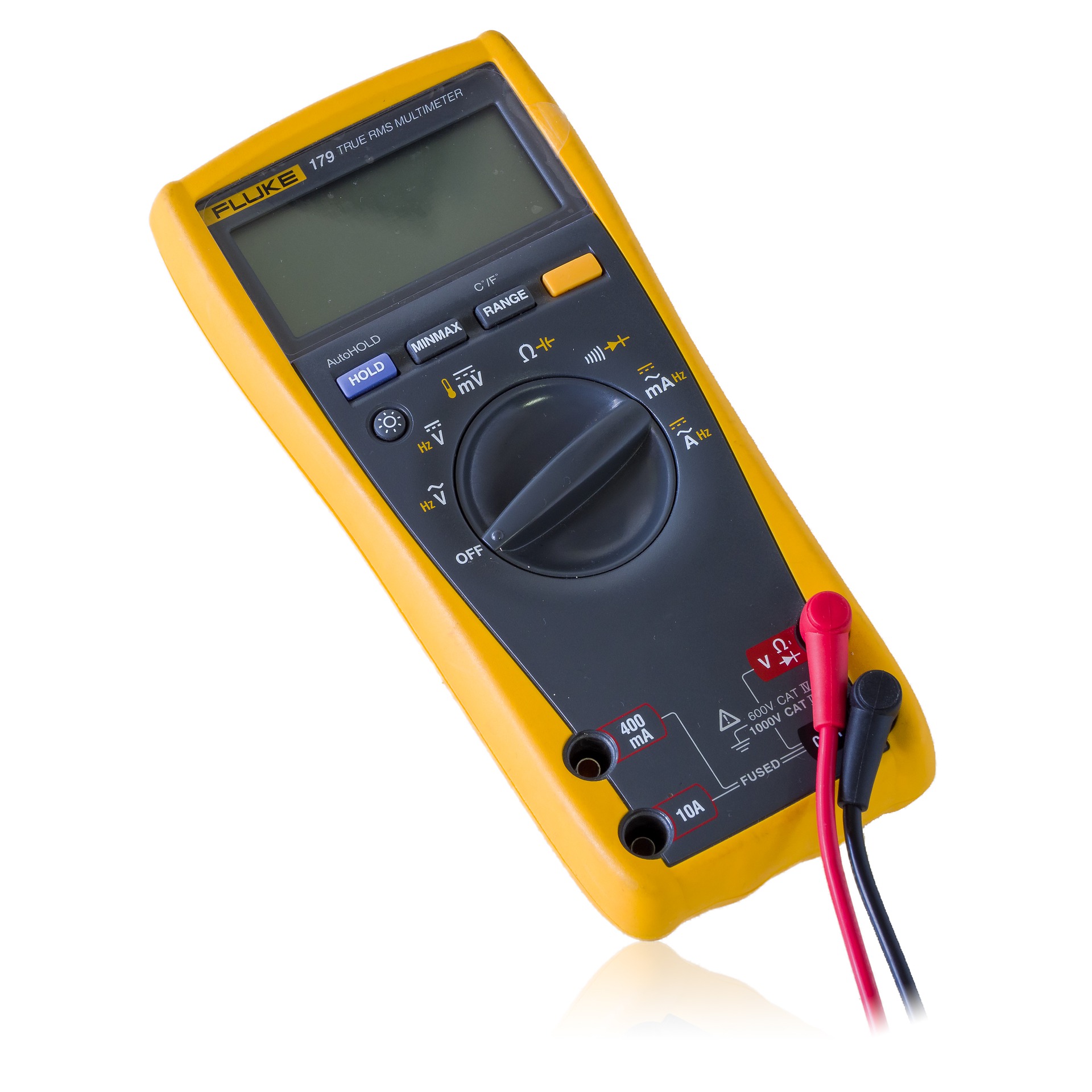
With voltage measurements, the total resistance of the voltmeter must be considered. Reading an analog voltmeter scale is like reading an analog ammeter scale. Some multirange voltmeters have only one range marked on the scale and the scale reading must be multiplied by the range switch setting to acquire the accurate voltage reading. Other voltmeters have individual ranges on the scale for every setting of the range switch. When utilizing these meters, ensure that you read the set of values that corresponds to the range switch setting. Many digital meters also have range switches, but they may additionally have a special feature known as autoranging. This means you can either utilize the range switch or let the digital meter set the proper range by itself.
As explained for analog current meters, the preciseness of that type of meter is based on full-scale deflection. With voltage measurements, the total resistance of the voltmeter must be considered.
Voltmeters must be in parallel with, or across, the component in the circuit being measured. Unlike the current meter, the analog voltmeter is less likely to being damaged if it is connected incorrectly. On the higher voltage ranges, the current flowing through the meter is drastically reduced because of the high total resistance. However, an erroneous reading will result if a voltmeter is connected in series with a circuit component rather than in parallel with it.
When connecting a DC voltmeter, always observe the proper polarity, as with a DC ammeter. You must connect the negative terminal of the meter to the negative, or low potential, side of the component, and the positive terminal to the positive, or high potential, side of the component. If you connect the analog voltmeter to the component with opposing polarities, the meter pointer will move to the left. It may bend if it strikes the retaining pin hard. Again, this is less likely to happen with zero-centered scales.
As with the digital ammeters, matching polarity is less of a problem with digital voltmeters. The digital readout of a reversed polarity will be preceded by a minus sign.
In an AC circuit, the voltage continuously reverses polarity. Therefore, it is not necessary to observe polarity when connecting an AC voltmeter across a component in an AC circuit.
Since a voltmeter is connected in parallel with a component, the voltmeter resistance should be as high as possible to avoid affecting circuit operation. The preciseness of a voltmeter is rated by its ohms /volt impedance. Electronic meters, which have built-in amplifiers, whether analog or digital, have input impedances up in the megohms, so they do not have much effect on the circuit operation.
Analog meters without built-in amplifiers can have ohms/volt ratings as low as 1000-ohms-per-volt. Any meter with a rating of 20,000 ohms/volt or lower will load down the circuit to generate an incorrect reading. A 100,000-ohm-per-volt meter is high for analog meters without built-in amplifiers, but electronic voltmeters with built-in amplifiers usually have an II-megohm input impedance and generate precise readings.
Sources:
https://www.electronics-notes.com/articles/test-methods/meters/multimeter-voltage-measurement.php
https://encyclopedia2.thefreedictionary.com/voltage+measurement


