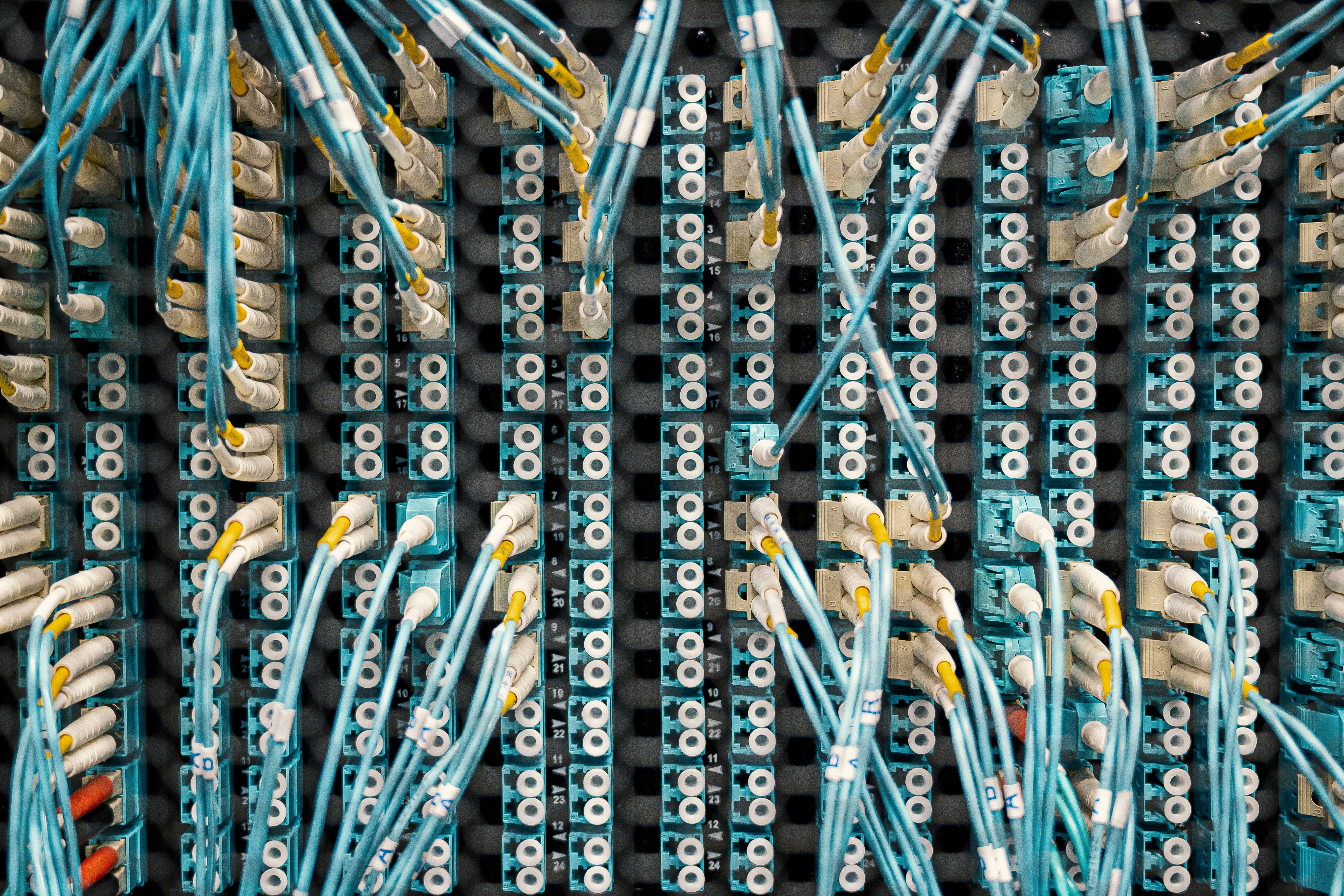
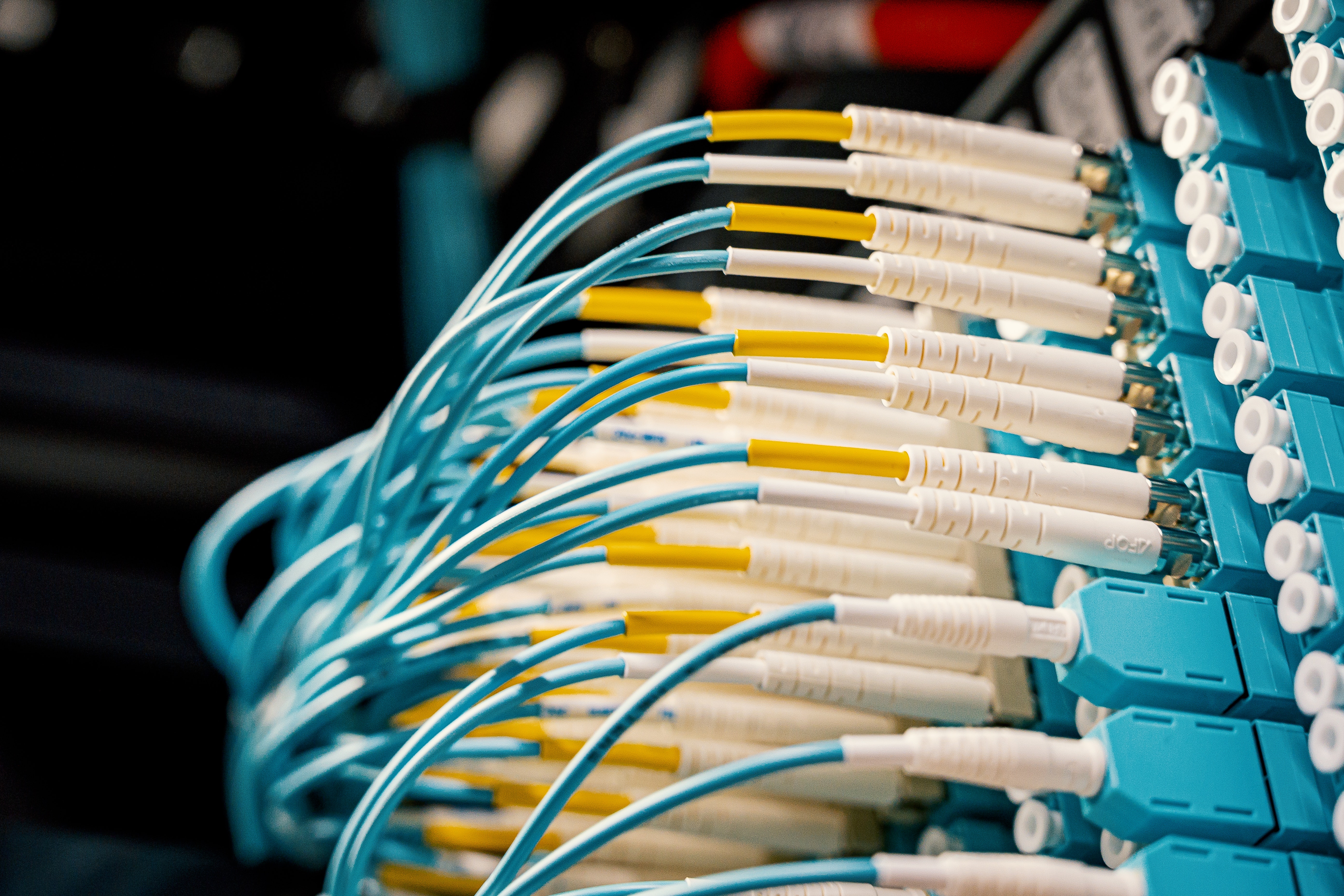
Fiber optics use hair-like glass fibers to cany modulated light to transmit signals over distances. Light signal systems use simpler equipment, less energy, and are less prone to interference. The glass fiber has a clear core to carry the light and a cladding that is highly reflective, as well as a protective coating. Light beamed into the core is reflected from side to side to keep it moving down the core. An electronic signal, such as a telephone signal, is converted to a light beam by a light generator, which can be a light-emitting diode (LED) or a laser diode. The light is transmitted down the fiber through various optical connectors, jumpers, patch panels, etc., and is picked up at the receiving end by a photodetector that converts it back to an electronic signal. Long cable runs use weld-like splices. Clear optical continuity is needed for light transmission.
Each of the optical components (connectors, pigtails, splices, fiber, connectors, etc.) cause some light attenuation. On long runs, a signal repeater (receiver/transmitter) is needed to build the light power back up. Light power attenuation is measured in dB; fiber attenuation is rated in dB per kilometer (about 3,280 ft.). The power of the light source is set high enough so after each attenuation level, the light beam still has enough power to drive the light detector, which is a photodiode. Detailed records are kept of the component attenuations and power levels, which can be used later for testing.
Poor connections, kinks, scratches, dents, dirt, breaks, and other faults can use signal interruption or increased attenuation. Test equipment used in fiber optics includes light sources, light power meters, and optical time domain reflectometers (OTDR). A light source provides a fixed, known power level which can be inputted at any junction. The light power meter can measure the level of transmitted light through any component or length of fiber to test continuity or attenuation. The power meter uses a photocell and gives readings in decibels (dB). The OTDR uses a laser pulse to test the losses of individual components and especially the light scattering and reflective characteristics of the fiber. It can measure distances to connectors, splices, and defects which cause added attenuation or open continuity.
There are several types of systems. One of these is a single, one-way (simplex) system. Two duplex lines would be needed for a two-way system. Usually, multifiber cables are used. Couplers can be used to feed additional stations, which is common in computer local area networks (LANs).
Sources:


