While measuring complex waveforms in digital techniques, mistakes can be made very easily. In this section, examples of this are presented. Some of them are explained in detail, to gain knowledge about the possible reasons for false triggering, which leads to wrong timing displays on the screen.
Imagine the display of a square wave and a double pulse in the correct time relation. Now, if the main time base (MTB) is triggered with the lower trace signal, then in the alternate mode, the lower trace could be started with the first of the double pulses and the upper trace with the second pulse.
The chopped mode could be used in this case, resulting in a vague, unstable picture that would indicate something is wrong. The way to avoid this is to trigger on the upper-trace signal, which has in each repetition time only one upgoing slope and one downgoing slope of the signals.
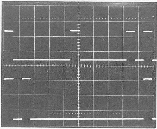
The following example is a little more complicated and the possible trigger errors are explained in more detail. Two pulse trains are generated, together with a square wave. If there is a photograph taken from a four-trace oscilloscope and the upper trace shows the square wave, while the middle and lower traces show the successive signals: a triple and double pulse, respectively. From now on the lower trace is called signal A, the middle trace is signal B, and the upper trace signal C. Triggering takes place at the negative slope of signal C.
Now suppose that only signal A and signal B are displayed and that the oscilloscope is triggered at signal A. Then, in the ALTERNATE mode, the result depends on the position of the electronic channel switch at the start of the first written trace. Thus, either signal A or signal B is written first, but both displays show the wrong timing.
When in the alternate mode the trigger source is channel A, then the sweeps are started at pulse number 1 and pulse number 2 alternately. Now, if with the first sweep, signal A is displayed- this depends on the internal position of the electronic channel selector switch. To make sure that the display shows the correct time relation, the chopped mode can be used. Although this results in a wrong picture, the user will be sure that erroneous triggering takes place and that corrective measures can be taken. If available, the user should utilize the signal internally if a four-trace oscilloscope is available or externally if triggered with a dual-trace oscilloscope.
References
https://www.eetimes.com/document.asp?doc_id=1195964
https://www.testandmeasurementtips.com/precision-accuracy-oscilloscopes/


