TTL Triggering
In logic systems employing building blocks (gates, Aip-Aop, etc.), a logic state level may be defined to determine whether a logic signal is supposed to be in its 0 (zero) or in its 1 state.
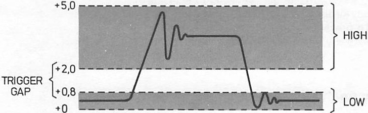
A distinction is made between the input and output of a device. The maximum voltage is the low state at the output (0.4 V) of a device is below the maximum level which is recognized also as low at the input (0.8 V) of the following device. In the same way, the minimum high level at the output (2. 4 V) is always higher than the level which is recognized as high at the input (2.0 V). These differences (both 0.4 V) are defined in this way as a “noise margin” to reduce the influence of noise. In this way, the TTL circuits are to these extents made immune to noise or interfering signals. For the same reasons of immunity to noise on the TTL signals, a digital oscilloscope may be provided with TTL trigger-level coupling. When the TTL trigger mode is selected, the trigger circuit responds in the same way as the input of a TTL building block. In this mode also, the LEVEL control knob of the MTB is not in operation. The SLOPE selection (+ or -) remains so that triggering at both positive and negative transients is still possible.
To reduce capacitive loading of the measuring point, it is advisable always to operate with a 10: 1 probe on TTL circuits. For the internal trigger sources (channel A or B) this means that an input sensitivity setting of 0.1 V/div always results in a stable display of TTL signals. In the external (EXT) trigger mode a 10: I probe is required to adapt TTL levels to the EXT trigger input.
Frequently, probes are connected to logic circuits without proper grounding. The inductance of a ground lead which is too long and the probe’s capacitance together form a series resonant circuit that is excited by the switching transitions in the logic, causing considerable ringing.
Ringing may provide many trigger points in the normal trigger mode when the LEVEL control is not set correctly, causing an ambiguous display. A TTL trigger mode obviates the need for any LEVEL setting and thus results in a proper display in most cases.
TTL triggering makes the oscilloscope partially immune to noise or ringing present in the trigger signal.
Logic Analyzer Triggering
The oscilloscope and the logic analyzer are totally different instruments and one cannot replace the other. On the contrary, they complement each other in digital techniques. This will be understood when the differences in setup are considered.
Even when used to display digital information, the oscilloscope starts displaying all information after a certain trigger instant. This applies also for the storage oscilloscope. The only shift in time of the display with respect to the trigger instant is caused by the delay line in the vertical channel. This delay has been built in to visualize the leading edge of a pulse-shaped waveform. Furthermore, the real time oscilloscope is basically an analog instrument for the display of signals in the time domain.
On the other hand, the logic analyzer is a digital instrument, specially developed for applications in the microcomputer field. It can represent digital information both in the time domain and in the data domain. Unlike an oscilloscope, not only can it display information after a certain trigger instant, but also before this point in time. For this purpose, the logic analyzer possesses in each “vertical channel” a pair of digital memories (registers), or 20 pairs if the instrument has 20 input channels. At a trigger command, the contents of one of the two memories in each channel remains preserved for display purposes.
Suppose that, after a trigger impulse at the set trigger input of the trigger control logic, the collection of data in the collection register is delayed for, say, 11 clock pulses (via the set pre-trigger delay input). This means that after the trigger moment 11 bits are still collected (post-trigger bits). But when a register is 16 bits long, 5 pre-trigger bits are still present in the register. When this information is transferred to the display register, the result on the screen will be a display of 5 pretrigger bits and 11 post-trigger bits. A vertical cursor over the whole screen, along with a digital number, indicate the bit at which it is triggered. It should be clear that this way of presentation of digital information can never be accomplished by a plain real-time oscilloscope.
References
https://www.radio-electronics.com/info/t_and_m/logic_analyzer/logic-analyser-triggering.php


