Dependable, stable, and simple to use- Cathode Ray Oscilloscopes are one of the most versatile test instruments. In addition to displaying wave shape, CROs can measure voltage level, period (and hence, frequency), and the phase relationship with other waveforms. CROs can also measure distortion, modulation depth, noise, amplifier bandwidth, and more.
How do CROs Work?
As the name implies, cathode ray oscilloscopes make measurements using a cathode ray tube (CRT) coupled with the necessary circuitry to ensure a continuous stable display. The principle operation of the CRT is thermionic emission. This term is used to describe the process of a negative hot cathode emitting electrons which are collected by an anode held at a positive potential relative to the cathode- resulting in an electric brunette being established in the form of an electron beam.
Cathode Ray Tube Construction
The cathode emits electrons that go through an aperture in the grid. This is known as the electron gun. The grid is made more negative than the cathode and controls the number of electrons emitted by the gun- resulting in the brightness of the display. The electron beam goes through an electrostatic lens to focus the beam on the screen. The screen is coated on the inside with a fluorescent powder called phosphor which has a visible glow when struck by high-speed electrons.
The electron beam generated by the electron gun and focused by the lens produces a stationary spot in both the horizontal and vertical directions. At this point, pairs of plates (2 X plates and 2 Y plates) are used to deflect the beam in a process known as electrostatic deflection. The beam passes between the two pairs of deflecting plates, and the potential differences on the plates determine the deflection angle.
CRO Real-Time Displays
The input for the real-time display of a cathode ray oscilloscope is first fed into an attenuator, which provides the necessary signal conditioning for the main vertical amplifier. This vertical amplifier is a wide-band amplifier that feeds the Y-plates of the CRT to provide vertical deflection. The vertical displacement of the spot on the screen at any instant is determined by the simultaneous Y input voltage. This real-time display occurs when the Y-input voltage is immediately displayed on the screen as a vertical deflection. However, with no corresponding horizontal movement, a vertical straight line will be displayed on the screen.
To provide the horizontal movement, the X-plates are fed with a saw-tooth waveform known as the timebase. This timebase, produced by the sweep generator, moves the electron beam at a uniform speed across the screen from left to right. At the end of the sweep, the beam is rapidly returned back to its starting point on the left-hand side of the screen (known as the flyback). The simultaneous movement of the beam in both the vertical and horizontal directions produces a trace of the input waveform. For a steady observable trace, the same portion of the input signal must be traced repeatedly by the time base. Therefore, it is necessary, to synchronize the horizontal movement with the input signal- meaning that each horizontal sweep of the screen must commence at an identical point on the input waveform. This is the function of the synchronizing circuity.
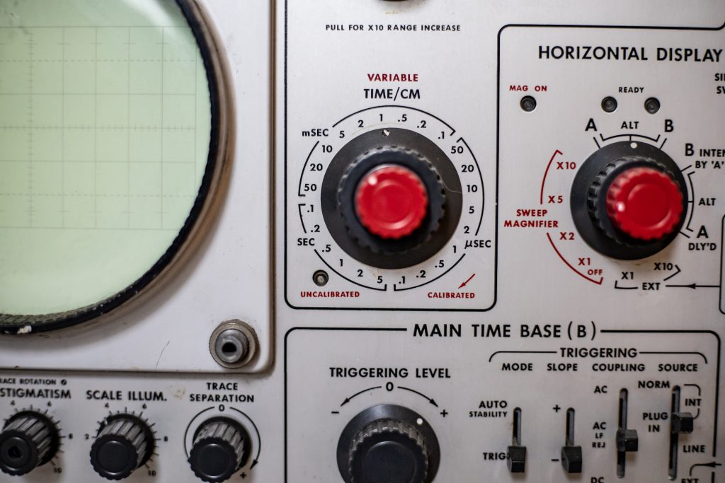
The CRT screen is provided with a measuring graticule with 8 vertical and 10 horizontal divisions. The setting of the vertical attenuator provides the voltage calibration, while the setting of the speed (or frequency) of the sweep generator provides time calibration.
Probes
Oscilloscopes, just like any other measuring instrument, should produce input signals without distortion. High-frequency and pulsed applications require an oscilloscope with minimal input capacitance to avoid any interference with the circuit under measurement, thus maintaining a high-frequency response. Probes are used to overcome this! Probes are used to increase the input resistance of the oscilloscope while lowering its input capacitance.
A common probe is the 10:1 attenuator. Using this probe, all voltage readings on the oscilloscope must be multiplied by a factor of 10 to give the actual level of the measured signal. A typical 10:1 probe with an oscilloscope input resistance of 1 MΩ will present an input resistance of 10 MΩ and an input capacitance of 8 pF. The same probe may be used with other instruments such as an EVM to reduce their loading effect.
The input capacitance of an oscilloscope is directly impacted by the Y attenuator setting. The reduced capacitive loading of an oscilloscope obtained by the use of the passive probe described above is achieved at the price of reduced sensitivity, usually by a factor of 10. To overcome this, “active probes” that have a high-impedance buffer amplifier to compensate for the loss in sensitivity can be used.
Additional Information:


