Whether you install, operate, repair, or design electrical equipment, you must know how to measure and test many types of electrical characteristics. The most imperative of these are electrical current, voltage, and resistance. Additionally, there are various applications that also require the testing and measuring of power, power factor, frequency, impedance, and sensitivity, as well as special component characteristics, such as capacitance and inductance.
Electrical tests are more closely related to the measurement of electrical power, within some equipment, within buildings, in utility areas, and in open transmission. Electronic tests also deal with electrical power but specialize in the measurement of advanced electronic signals carrying intelligence information.
The change in technology over the last 20 to 30 years has brought about many changes and improvements in test and measuring equipment. The methods of reading out the test data have changed greatly, making testing and measuring easier and more precise. The analog or pointer meter is an intricate, fragile device, and was the original method. The pointer meter is still in common use, but digital meters have become more popular because of their greater sensitivity, preciseness, and ease of use.
Recorders and oscilloscopes are for more specialized applications. Oscilloscopes can perform waveform analysis, while recorders are used to monitor tests over an extended period. Lamps provide an even simpler way of indicating some measurements and audible beeps and tones are used for attention-getting applications and alarms.
Analog meters do not measure the electrical characteristics directly. They do their measuring indirectly by measuring the effect of what is being measured. The effect and the amount of the effect are considered analogous to the original characteristic being measured. Usually, the current is the main characteristic tested, and the effects of the current, either magnetic or thermal, are converted to movement with a deflected pointer. The greater the current being measured, the greater is the magnetic or thermal effect, and the greater the pointer deflection. Therefore, the movement or distance of the pointer action is analogous to the amount of current being measured.
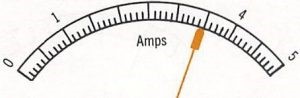
Reading the scale of a single-range current meter is simple. Since the meter only measures one range of current, only one set of values is required on the scale. However, some multirange current meters also only have one set of values on the scale, even though they measure several ranges of current. When this is the case, you must multiply the scale reading by the setting of the range switch. For example, if the scale is calibrated in values from O to 5 amperes, and the range switch is in the 5-ampere position, you would read the current directly. However, if the range switch is in the 25-ampere position, you must first determine the multiplication factor for the scale by dividing the range setting by the full-scale value of the meter (25/ 5 = 5). Then, in this example, multiply the scale reading by 5 to find the amount of current flowing in the circuit. Other current meters might have a separate set of values for each position of the range switch. In this case, make sure that you read the set of values that corresponds to the setting of the range switch.
Although the current flowing in a circuit may be read anywhere on the scale from zero to full deflection, the closer the pointer is to full-scale deflection, the more accurate the reading will be. The accuracy of a meter is specified as the percentage of error at full-scale deflection. For example, if the specified accuracy of a 5-ampere meter is ± 2%, the meter reading can be off by ± 0.1 amperes if it reads full scale. However, the error in a meter is fixed. If it can be off as much as ± 0.1 amperes at 5 amperes, it can be off as much as ± 0.1 amperes at any reading below full-scale deflection. Therefore, although the accuracy of a meter is specified at full-scale deflection, remember that the percentage of error becomes progressively greater as the pointer moves down the scale.
Considering this, if you had an idea that the current to be measured should be about 3 to 4 amperes, and you had a meter with a 0-5 and a 0-25 ampere range, you should use the 0-5 ampere range because the reading will fall closer to full-scale deflection. Similarly, if you had two meters, one with a 0 to 5-ampere range and the other with a 0 to 25-ampere range, you should use the meter with the 5-ampere range, to get greater deflection and greater accuracy.
Another reason for selecting the scale that gives the greatest deflection is that it is easier to interpret the reading on a lower scale if the pointer falls between graduations. For example, as you can see, it would be much easier to judge values between 4 and 5 amperes on the O to 5-ampere scale than it would be on the O to 25 ampere scale because on the latter, each graduation stands for 5 times as much current.
The numbers on the scale are typically tiny because of space issues. Most meters of all kinds have some built-in inaccuracies, but the reading inaccuracies of the pointer and scale compound those inaccuracies. In some cases, the inaccuracies can be tolerated, sometimes, they cannot.
Digital meters provide direct readouts with the actual numerals. The numerals are large and easier to read. They are numerically specific and do not need to be viewed closely or interpreted to determine the reading. The built-in level of preciseness of the digital meter is not degraded by any reading or interpretation inaccuracies.
The three major test and measurement characteristics- current, voltage, and resistance are related to each other by Ohm’s law, as taught in basic electricity. This simplifies meter design since the meter can set up circuits so that a single characteristic can be used to decide the other characteristics to be measured. For example, the current can be used to indicate voltage or resistance and vice versa. Since resistance (R) = voltage (V) divided by current (I) (R = V/ 1), if the meter uses a standard, known voltage source, then the amount of current that flows will indicate the amount of resistance that allowed that current. On the other hand, since V = IR, if the meter uses a standard, known resistance in its circuit, then the amount of current that flows will specify the amount of voltage that caused that current flow.
Analog, or pointer meter movements, rely on the effects of current flow, not only to measure current but to measure voltage and resistance by utilizing Ohm’s law. However, other meters that use built-in amplifiers usually react to voltage as the basic measurement characteristic, again, using Ohm’s law to calculate current and resistance. This applies to both analog and digital meters with built-in amplifiers.


