Last week, we published a blog post going over the tools and methods used to measure electrical voltage in various situations. This week, we are taking a look at tests for measuring electrical currents- an essential step in electronic equipment maintenance that can identify the root cause of any failures and malfunctions. We will look at how to use ammeters, the importance of wire size, and how to test currents in power lines, heater motors, and air conditioners.
Using Ammeters
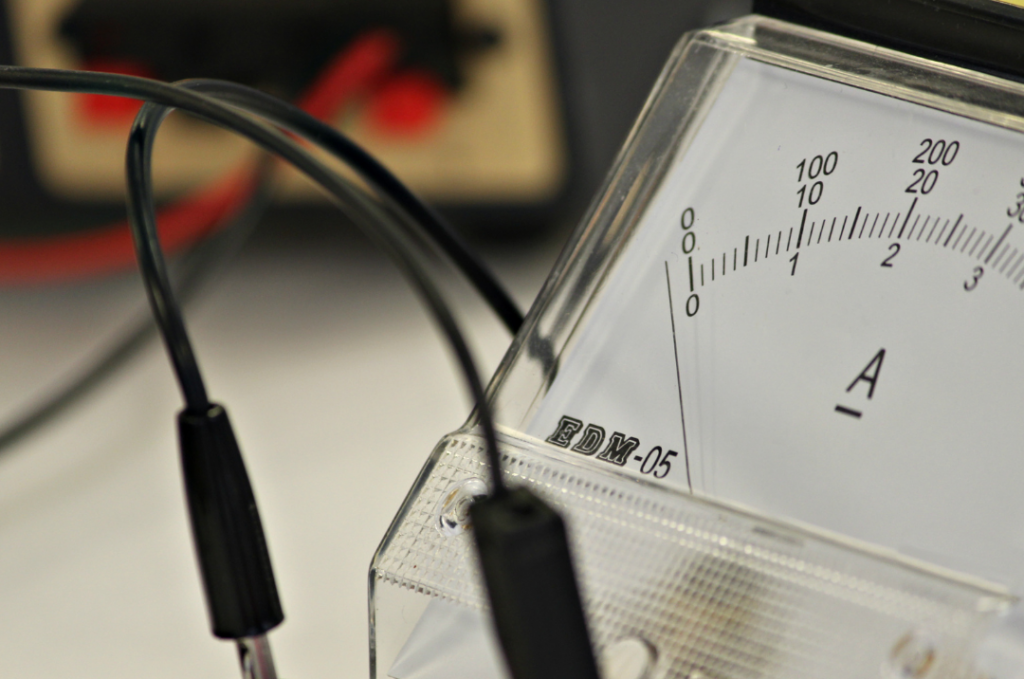
Ammeters determine how much electricity is flowing through a circuit (current), and measure in amperes (amps). Whereas voltage can be tested by simply touching the test probes to specific points on an energized circuit, the steps for measuring currents differ depending on whether an in-line ammeter or a clamp-on ammeter is used. Clamp-on ammeters are simple, they only need to be clamped to an energized wire in order to measure the current (no wire disconnection is necessary). In-line ammeters, on the other hand, require specific steps to ensure safe and accurate readings.
Steps to measuring with an in-line ammeter:
1) Turn off the power.
2) Open the circuit.
2) Connect the meter to the specific circuit line you want to measure, making sure that it is firmly supported.
3) Turn the power back on.
4) Once the reading is received and noted, turn the power back off before taking the next step.
5) Remove the meter.
6) Reconnect the circuit.
7) Turn the power back on.
Safety note: It is important to make sure that the power is completely and totally shut off, and that all capacitors are discharged, before interacting with any disconnected / loose / bare electrical wiring.
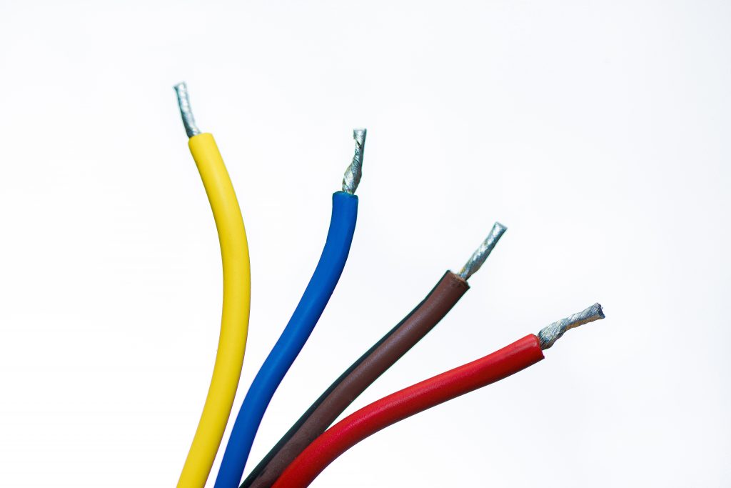
Sizes of Wires
When electrical current flows through a wire, the resistance of the wire results in heat production. The smaller the diameter of a wire, the greater the resistance- producing more heat for a given current flow. Conversely, wires with a larger diameter will produce less heat with the same amount of current, resulting in a higher current rating. Wire gauges have individual ampere capacities, which, like wire sizes, go down as the gauge number goes up. These amp ratings can differ depending on the specific insulation used.
Testing Currents in Power Lines
Both the circuit breaker and the specific wire size that is used in a power line (either the main service entrance or an individual branch circuit) are determined by the max amount of current the circuit is expected to carry under a full load. This is how the circuit breaker rating is decided. However, as time goes on, additional loads could have been added to the system beyond what was expected.
To test a power line current, the first step is to make sure that the main line breakers have been switched off. If using an in-line ammeter, first disconnect a branch wire from the circuit breaker, and then connect a small test lead in the breaker to the circuit that is being tested. The ammeter should be connected between these two leads.
The ammeter should be set to its highest range in case a short circuit is causing a current to flow excessively. Turn the power back on for the main line breakers. The ammeter should read a number below the breaker / wire rating as equipment connected to the branch circuit is turned back on one by one. If the reading on the ammeter approaches the same number as the breaker rating before all of the appliances have been switched back on, it indicates that the line is overloaded.
The solution to this issue is not to replace the circuit breaker with a bigger one. The circuit breaker rating should match the size of the wire. As previously discussed, wire gauges have a certain amount of amps they can carry. Overloading the gauges would cause the wires to overheat. Instead, the branch circuit can either be separated into two separate branches, or the number of appliances used can be restricted.
Testing Currents in Motors
In general, motors are rated in units of horsepower (hp). Horsepower is measured with the formula hp = Fd / t. “F” refers to the amount of force (in pounds), “d” refers to the measure of distance (in feet), and “t” refers to the amount of time (in minutes).
The hot water circulating pump motor used in a heating system, under normal operating conditions at 1725 rpm, usually draws 1.75 amperes. These motors often go bad due to their cyclical use- high use in one season followed by a long period of sitting idle. To measure the current in this case, disconnect the wire between the junction box and the motor, attaching the ammeter between the two leads. The normal conditions necessary to produce the horsepower rating of a motor are usually stamped on the casing or nameplate.
Testing Currents in Air Conditioners
The motors in air conditioners utilize special starting surge currents on their startup that allow them to reach their rated rpm more quickly than other motors. If an air conditioner had a rating of 15 amperes, that initial starting surge would actually measure greater than 15 amps. For this reason, it is recommended that air conditioners are run on an individual, dedicated circuit. To measure the current in this case, it is easiest to use a test jig (which is available to purchase commercially) to test at the electrical socket and avoid disturbing the wiring of the branch circuit. The range of the ammeter should be set above 15 amps to account for the initial surge. A normal read when the compressor is on should be below 10 amps. If the circulator fan is running, the reading should be around 3 amps.
Source:
Mileaf, Harry. Electrical Test Equipment, H.W. Sams, Indianapolis, Ind, USA : 1989, pp. 39–43.


