As products innovate, testing also becomes more complex. With a greater need for precise timing and synchronization, proper measurements, and reduced downtime, what are the next steps for your test system? In a recent webinar titled “3 Ways to Optimize Signal Analysis with NI Oscilloscopes”, the NI team discusses how these issues can be addressed using NI hardware and solutions.
Characteristics of Oscilloscope Probes
The webinar begins by discussing the different types of oscilloscope probes and how to know which one is right for your specific application. There are many important characteristics of oscilloscope probes to consider when choosing the right one for your test system. Bandwidth describes the difference between the upper and lower frequencies of the probe and is measured in a continuous band of frequency. The attenuation ratio of an oscilloscope probe is the ratio of the input signal amplitude to the output signal amplitude.
Another important consideration is the impedance of the probe. The impedance is listed as two values: the input resistance and the input capacitance. These values create a complex quantity that is entirely dependent on the frequency. The capacitance of the probe, which is separate from the input capacitance, is measured across the tip of the probe itself. Capacitive loading results in a waveform that is slow to converge, while resistive loading results in a waveform that never truly converges. Altogether, the test system acts as a low-pass filter.
Passive and Active Probes
When considering passive probes, it is important to keep the attenuation ratio in mind. Higher attenuation ratios (25-to-1, 100-to-1) act very similarly to a 10-to-1 ratio. A 1-to-1 ratio has a very low bandwidth, designed for minimal loss and easy connections. 10-to-1 probes have a built-in parallel resistor that helps to cancel out input capacitance and allows for higher bandwidth, but they need compensation.
Probe compensation is the procedure by which the probe capacitor’s value is changed to cancel the scope’s input capacitance. A properly compensated wavelength will result in a square wave that is as flat and square as possible. Ground lead inductance is another important thing to keep in mind when considering passive probes. The length of the spring hook and ground lead will work together in parallel at higher frequencies to produce an inductance. The key is to keep the ground lead inductance as small as possible to avoid affecting your signal.
Passive probes are the ideal choice for applications that have bandwidths under 500 MHz and voltages under 30 V.
Active probes use an internal amplifier to achieve a very low input capacitance, allowing for high-frequency measurements to be taken in GHz. Due to the internal amplifier, active probes require an external power supply. Active probes are the ideal choice for applications that have a bandwidth that is above 500 MHz. Differential probes allow for measurements to be taken without a reference to the ground plane.
Synchronization
Having all your test data synchronized is essential. However, synchronization is one of the most difficult aspects of a test system! Some of the different synchronization options found with NI Hardware include:
Software-based. Described in the webinar as perfect for “quick and dirty” measurements, software-based synchronization uses a platform such as InstrumentStudio to send a trigger to the device. However, the accuracy is within milliseconds.
Time-based. Time-based synchronization works especially well for large distributive systems that use their own onboard clocks.
Signal-based. Signal-based synchronization sends signals over PFI lines or through PXI backplanes. This method works very well with one chassis, but multiple chassis can have complications.
NI-TClk. The NI Trigger Clock software driver for LabVIEW is an excellent choice for synchronization when systems require more modular channels. It is also incredibly helpful for syncing two different instruments, or for simply exporting/sharing a sample clock.
CableSense
CableSense was developed and created by NI to address the issue of test system downtime. Unlike traditional time-domain reflectometers (TDRs) that require the user to dismantle and then reassemble the test system to address issues- CableSense is built into the PXI oscilloscope. The only downside is that due to the use of bandwidth, rise times are slightly slower than they are with a traditional TDR.
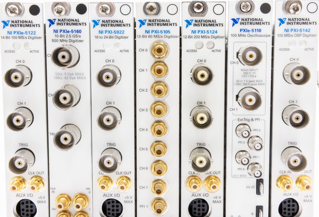
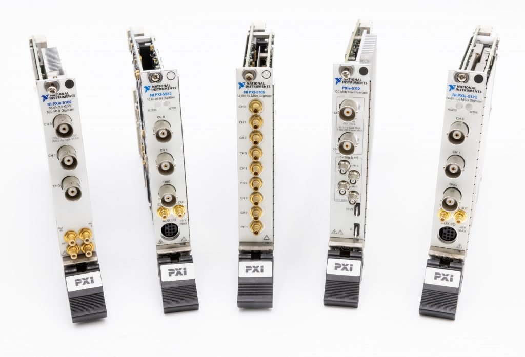
CableSense has the ability to check the functionality of cables, ensure that the cables are being swapped to the correct locations on the device-under-test (DUT), and determine the overall health of the cable. The PXI oscilloscopes and digitizers mentioned in the webinar that support CableSense are the PXIe-5160, PXIe-5162, PXIe-5110, PXIe-5111, PXIe-5113, and the PXIe-5774.
The speakers in this NI Webinar are Leen Adnan (NI Solutions Marketer), Jacob Sees (NI Product Manager), and Jonathan Rivera (NI Product Marketing Engineer).
Additional Information


