Before the modern digital technology we use in computers today, electronic computations were conducted by utilizing both voltages and currents as representations of numerical values. This process needed circuitry capable of carrying out a wide range of analog signal processing tasks, which led to the use of operational amplifiers (often referred to as op-amps). The engineering concept of negative feedback, which forms the basis of practically all automatic control procedures, holds the key to the utility of these tiny circuits.
Op-amps can be built to carry out a wide range of tasks for analyzing analog signals, all with the use of only a few external components. Contemporary designs of these amplifiers have increased durability, with many being produced with the ability to withstand short-circuits directly on their outputs without being harmed. Multiple op-amps can be linked together, with the specific arrangement of the components around them determining how each one performs.
How Do They Work?
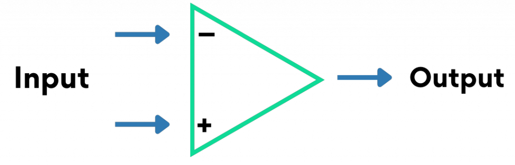
Since an op-amp is only an amplifier circuit, it can be constructed in a variety of ways. One might be built using discrete parts, such as separate transistors, capacitors, and resistors. No matter how it is created, the fundamental connections of an op-amp remain the same. In addition to a power supply, operational amplifiers need inputs and one output. Why use 2 inputs? When there is a discrepancy between the two inputs, an op-amp reacts. There is no output if the inputs of both sides are equal. One side is known as the non-inverting input, denoted with a “+” The other side is known as the inverting input, denoted with a “−,”. The output will be positive if the “+” input is greater than the “-” input.
In lieu of complex diagrams, a triangle is often used to denote an electronic amplifier. A schematic of an op-amp could look like this:
Op-Amps and Differentiation
The use of voltages and currents as representations of numerical qualities is incredibly useful when it comes to simulating physical processes. For example, the rate of change of voltage in relation to a current going through a capacitor is known in mathematical terms as the derivative. Knowing this, we can have the voltage that is across the capacitor represent an object’s velocity. In this scenario, the force necessary to accelerate or decelerate an item would be represented by the current flowing through the capacitor, and the mass of the object would be represented by the capacitance of the capacitor. This can be seen in the formulas below:

Where i𝒸 represents the instant current that goes through the capacitor, C represents the capacitance (measured in farads), and dv / dt represents the rate at which the velocity changes over time.

Where F represents the force that is applied to the object, m represents the object’s mass, and dv / dt represents the rate at which the velocity changes over time.
The term used in calculus to describe this analog calculation of this derivative function is differentiation. It is a result of the relationship between the current flowing through a capacitor and the applied voltage across it. Unlike a digital computer, this circuit doesn’t need to be “programmed” in order to carry out this pretty complex mathematical function.
Op-Amps and Negative Feedback
If the “+” input is higher than the “-” input, the output is negative.
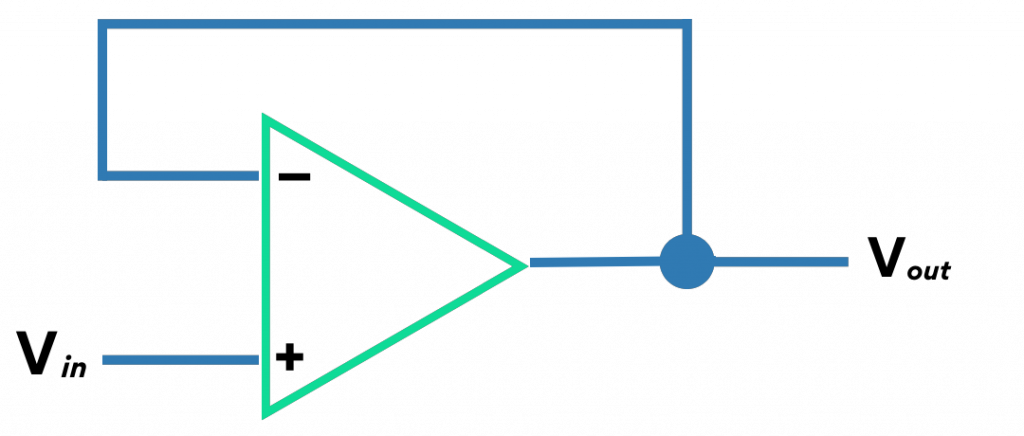
According to the concept of differential gain, the output voltage of the operational amplifier will rise as the input voltage does. However, the output voltage is sent back to the inverting input as the output voltage rises, reducing the difference between the voltage inputs and tending to reduce the output. For every given input voltage, the op-amp will output a voltage that is almost exactly equal, but just low enough to leave enough of a voltage differential for the difference to be amplified to produce the output voltage.
The circuit will eventually reach equilibrium and stabilize at a point where the output voltage is precisely the appropriate amount to maintain the proper amount of difference, creating the proper amount of output voltage in turn. Negative feedback is a method for creating a self-stabilizing system. In engineering, negative feedback provides a rare occurrence in which everything benefits. Each of the amplifier’s other parameters improves when the voltage gain is sacrificed- such as noise, distortion, and frequency responsiveness!
Additional Information:
https://www.markhennessy.co.uk/articles/op-amps.htm
http://www.ibiblio.org/kuphaldt/electricCircuits/Semi/SEMI_8.html


