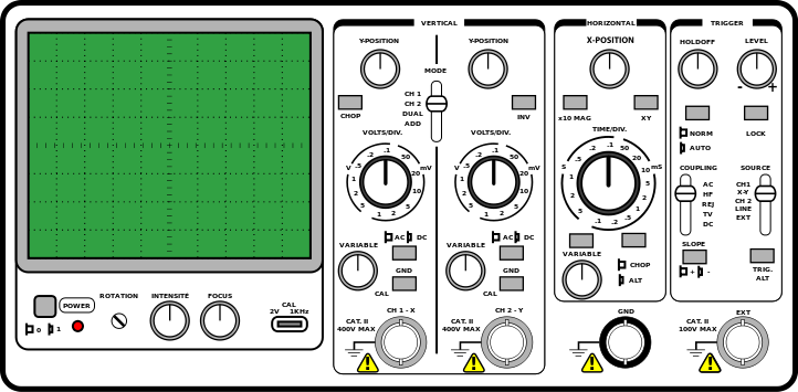
The two sampling techniques most commonly applied are random sampling and sequential sampling. In the random-sampling technique, no time relation exists between the timing-ramp voltage (trigger-source functioning) and the sampling instant. Owing to this, the picture on the screen is built up with samples which appear at places scattered at random over the waveform. In the sequential-sampling technique, which is the technique most frequently employed, the successive samples appear on the screen at adjacent places over the waveform because a comparison circuit links the sampling instants to the timing ramp voltages when triggered by the input signal.
A disadvantage of this system is that a high trigger repetition rate is required to obtain an adequate picture of the signal. A CRT screen with a somewhat higher persistence can partly overcome this disadvantage.

Sequential sampling is taking samples of the signal one after the other, again on successive repetitions of the signal. Care must be taken to set up the oscilloscope correctly before proceeding with sequential sampling. After each hold-off period, a successive trigger pulse starts the timingramp generator. The comparator compares the ramp voltage with the output of the staircase generator, which also delivers the horizontal deflection voltage. When the ramp voltage equals the staircase voltage, the comparator delivers a pulse to the sampling pulse generator and to the pump generator.
The sampling pulse opens the sampling gate, and a sample of the delayed input voltage is taken and fed to the Y memory for the vertical deflection at the CRT. The pump generator initiates the staircase generator to the next higher step, so the next sample will be displayed next to the former one. In this way, the samples taken from the input signal are displayed in sequential order from left to right on the screen. It is obvious that the input signal must pass a delay line before the sampling gate if the complete leading edge of an input signal is to be displayed. Otherwise, just as in the real-time oscilloscope, the finite trigger level to be reached to derive a trigger pulse, added to the propagation delays in the time-base and trigger circuits, would prevent this happening.
However, the implementation of the delay line is a disadvantage, because it must pass the full bandwidth. This may lead again to bandwidth limitations and inherent distortions. Nevertheless, the advantages of this method in practice outweigh the advantage of the random-sampling method. However, in both methods, the advantages of sampling are clearly seen. Only the sampling circuits of the oscilloscope must operate at the high speeds required for the VHF signal to be measured, while the rest of the oscilloscope circuits are relatively low-frequency ones.
References
https://www.evaluationengineering.com/capturing-and-evaluating-high-frequency-signals.php
https://www.researchgate.net/publication/3427540_The_Sampling_Oscilloscope_as_a_Microwave_Instrument


