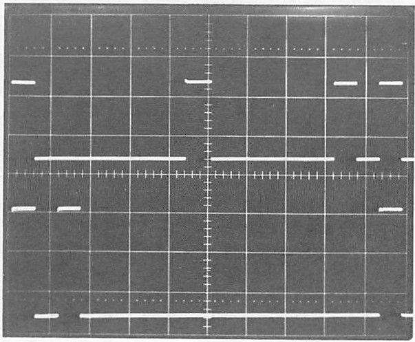
Apart from single-shot measurements, the signal that is going to be measured must be repetitive. Signals a, b, and c in Fig. 1.9 are all repetitive because a span of time can be defined so that the same signal is repeated sequentially.
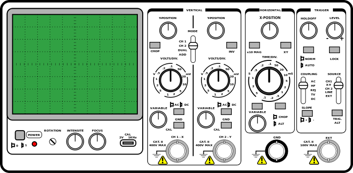
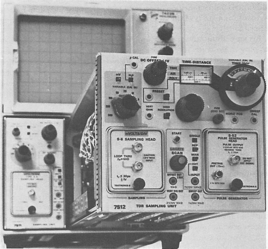
Continue reading “How To: Modifying an Oscilloscope for Measurements”