PXI Digital Multimeters (DMMs) are versatile instruments that offer highly precise measurements for a variety of applications. From diode testing to voltage measurements, these modular devices utilize the same synchronization features and high-speed data capabilities as the PXI platform at large, making them an excellent choice for even the most challenging tasks. This post focuses on the specifications and features of the PXI-4070 from NI, a 6.5 Digit FlexDMM that boasts high speeds, accurate precision, and flexible functionality.
In this post, we will dive into measuring for DC and AC voltage or current, 2-wire or 4-wire resistance, diode, frequency, DC coupling, period, and continuity. Read on to learn more about how to unlock the full potential of measuring with the PXI-4070!
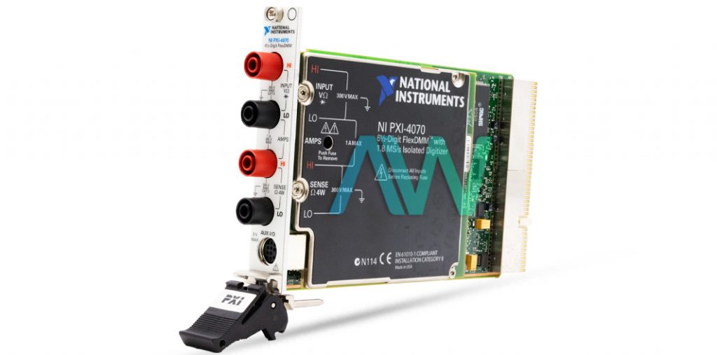
The Front Panel of the PXI-4070
The front panel of the PXI-4070 DMM features a single 9-pin digital signal connector. This connector utilizes TTL-Level triggering signals to facilitate the use of external scanning equipment- providing flexibility when the user needs it most. This front panel also features 4 shrouded banana plug connectors which function as high-voltage safety connectors. These connectors determine what the PXI-4070 will measure, so it’s important to become familiar with their individual attributes.
Getting Start with the PXI-4070
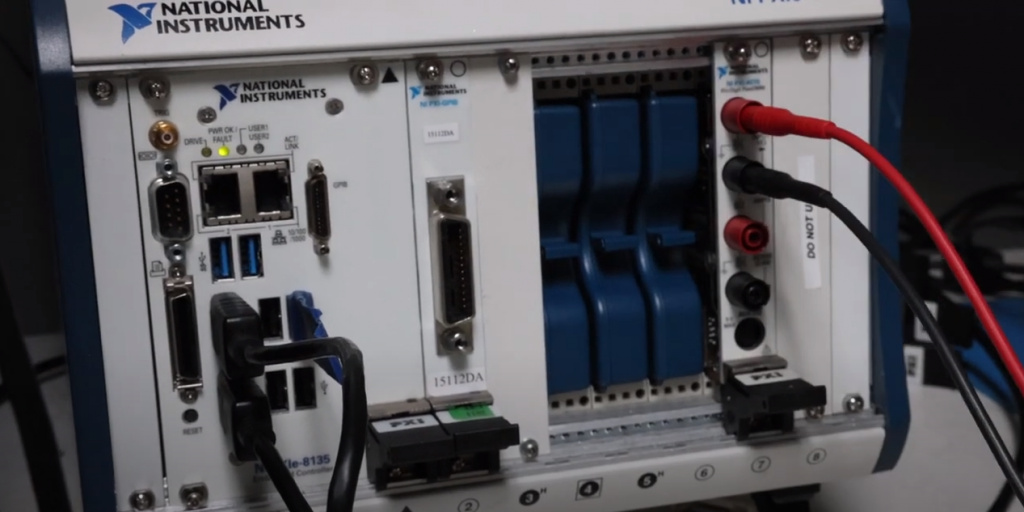
Before inserting the PXI-4070 into the PXI chassis, you will want to make sure that the chassis is plugged into a power source but powered off. The PXI-4070 can be inserted into any available slot of the chassis- once the ejector handle locks into the “up” position, the captive screw can be tightened to keep it secure. After the DMM is secured, the PXI chassis can be powered on and connected. It is important to note that the AUX I/O connector of the PXI-4070 is not isolated- meaning that the connection is not grounded to the measurement circuit, but rather it is grounded on the PXI chassis. Because of this, the digital signal of the connector should not be operated above a range of -0.5 V to 5.5 V from the PXI chassis ground.
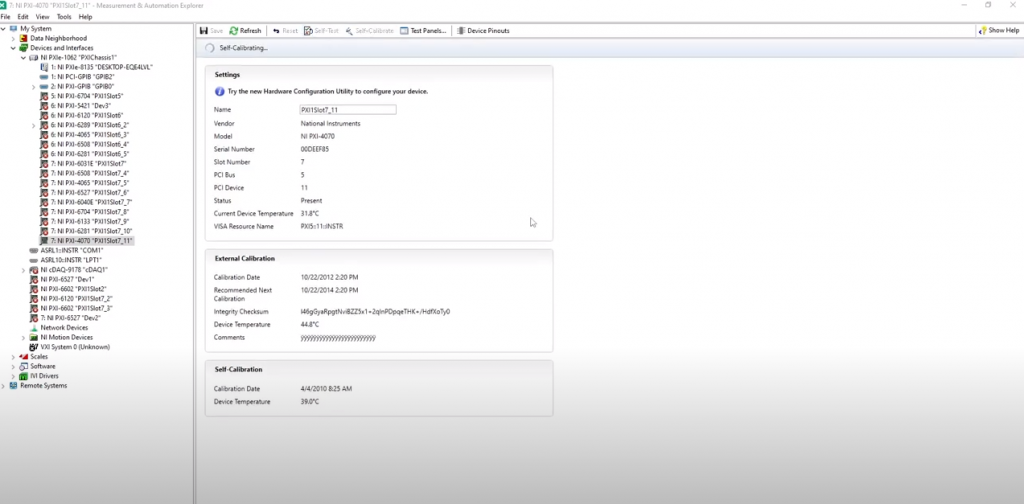
Once connected and running, you will want to launch NI Measurement and Automation Explorer (MAX) and choose the “Expand Devices and Interfaces” option. The PXI-4070 should appear under this option. Once the device passes a self-calibration, launch the soft front panel in order to run some functional tests.
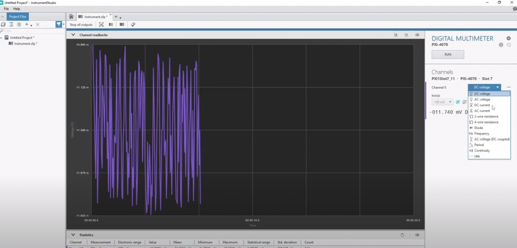
InstrumentStudio will list out the options to measure DC voltage, DC current, AC voltage, AC current, 2-wire resistance, 4-wire resistance, diode, frequency, DC coupling, period, and continuity.
Measuring AC and DC Voltage and Current
To begin measuring AC and DC voltage using the PXI-4070, first plug pomona patch cords into the top two banana plugs with their corresponding colors, with the other ends connected to a power supply. For this post (and in it’s corresponding YouTube video), we will be using a calibrator that outputs all of the settings we need.
When set to 300 volts, the PXI-4070 measures the DC voltage to be 300 volts. From here, you can switch to measure AC voltage. If, for example, the device was set to 120 volts, then the AC measurement (which fluctuates back and forth) is also 120 volts.
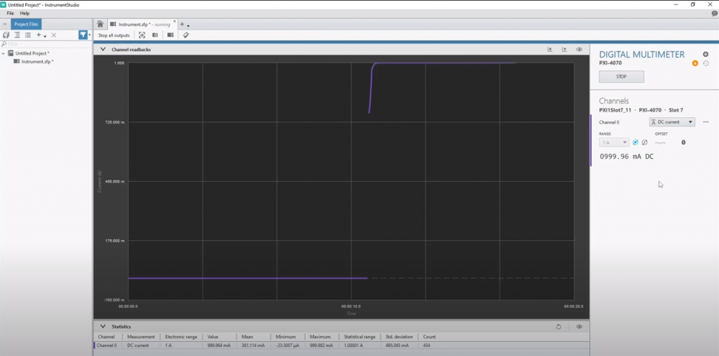
In order to measure either AC or DC currents, you must first move the banana cables down so that they are plugged into the middle two plugs. For the DC current, if the ampere is set to 1, then the measurement will read as just under 1 amp (0999.95 milliampere) because the flow is going in the same direction. If you switch to AC current from this screen, you will see that the fluctuation of the waves causes 1 amp to measure at 1,000 milliampere.
Measuring 2 and 4-Wire Resistance
The configuration of the cords in order to measure 2-wire resistance is the same as measuring for voltage, utilizing the top two banana plugs of the PXI-4070. For this measurement, we have the calibrator set to 1,000 ohms. When viewed in InstrumentStudio, you should find the part measures the 1,000 ohms correctly.
Measuring for 4-wire resistance is the same process, except all four banana plugs must be plugged in, like so:
Measuring Diode
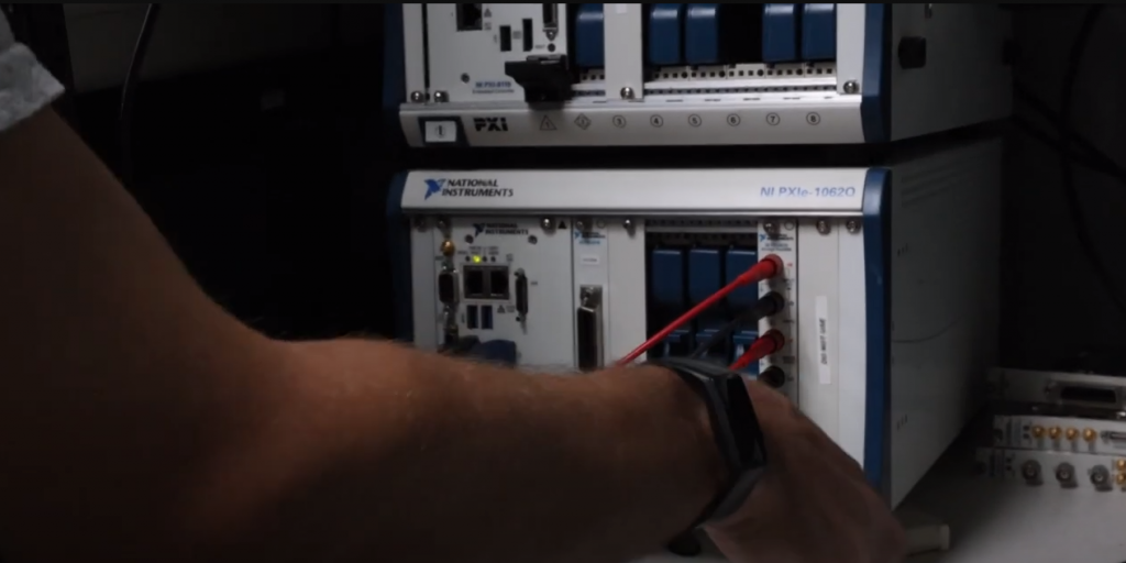
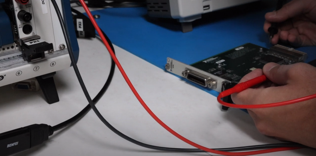
The term “diode” refers to the measurement of how much voltage drops between two points- it is the method used to test a circuit board for shorts. You will need to use probes in order to measure for this, ensuring that the ends of the probes are plugged in to the top two banana plugs of the PXI-4070. For this example, we will measure between the change between the ground and a PXI-GPIB.
Using this method, we find that there is a change of 1 volt. This is good news, because a measurement of 0 voltage drop indicates a short!
Measuring Frequency
The term “frequency” refers to how many times a wave oscillates per second. To measure this with the PXI-4070, we plug it back into the calibrator. For this example, we set it to 5 volts at 1,000 hertz.
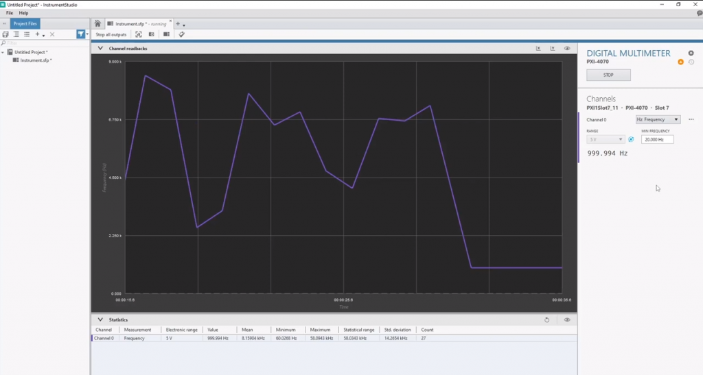
As you can see by the graph, the device measures just under 1,000 hz at 999.991 hz.
Measuring “AC Voltage DC Coupled”
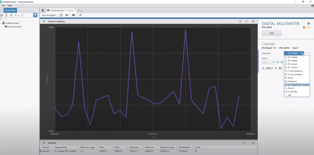
This measurement option describes when there is a transfer of energy between two mediums through physical contact. DC coupling is what allows both AC and DC signals to pass through this connection. For this example, we left the range at 5 volts- and we see that the device measures at exactly 5 volts.
Measuring Period
The “period” measurement describes the distance between the point of one sine wave to the same point in a second sine wave. For this example, we will leave the hz at 1,000.
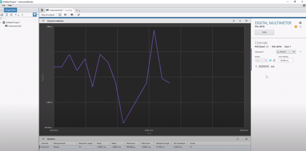
Looking at the graph, we can see that it is measuring as 1 millisecond between the two sine waves. If, for example, the hz was lowered from 1,000 hz to 60 hz- the waves would become wider and the measurement would greatly increase to 16 milliseconds.
Measuring Continuity
The term “continuity” refers to the measurement of a connection between two points. This is often how technicians check to see if points are grounded, such as measuring if a pin is connected to its board after being soldered on. For this last measurement, we will once again use the probes, plugged into the top two banana plugs.
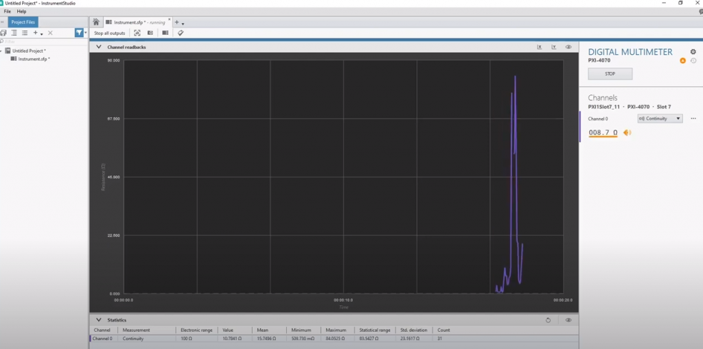
Whenever the graph spikes, it indicates that there is a connection between the two points.
Have questions? Want to know more? Subscribe to the Apex Waves YouTube channel for videos highlighting different products or walking through some obsolete tech how-to’s.


