Methods For Testing Voltages

Closeup of person holding a yellow digital multimeter to check voltages of wiring

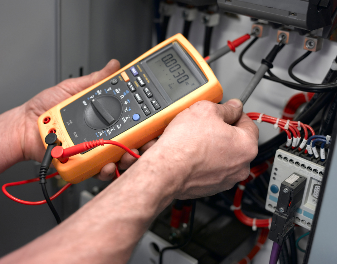
Measurements of electrical voltage are used to determine the possible differences in electric charge between two different points in an electric circuit. This data makes it possible to ascertain how much power is being used by a specific object, compared to how much power is available in the circuit. Since it allows us to ensure that an electrical circuit is operating both correctly and safely, this information is essential for the design, installation, and operation of electrical systems.

Continue reading “Methods For Testing Voltages”

Simplifying Circuits with Boolean Algebra

Closeup of tech device that monitors movement on top of written

1 + 1 = 1. While this statement would be false when discussing the real numbers of ordinary algebraic concepts, It makes perfect sense in the context of Boolean Algebra. This mathematical concept is most practically applied when simplifying logic circuits. When the function of a logic circuit can be translated into Boolean form, then the resulting equation can be simplified by applying certain algebraic rules- allowing a circuit with fewer components to perform the same function.

Continue reading “Simplifying Circuits with Boolean Algebra”

How-To: Submitting a RMA Request

Closeup of a green circuit board being repaired

Even the most well maintained systems will encounter issues every now and again. When the unexpected happens, the last thing you want is to jump through hoops to get a repair- which is why Apex Waves is making it even easier to request a return merchandise authorization form. In this post, we will go over how to utilize the new Apex Waves online request form and answer some common questions about the RMA process.

Continue reading “How-To: Submitting a RMA Request”

Are AI Images Real Art?

4 panel photo created by the Midjourney AI with oscilloscopes and oceans

In August 2022, Jason M. Allen won first place at the Colorado State Fair Fine Arts Competition. The category for his submission was “digital arts/digitally manipulated photography”. Normally this award wouldn’t make national news headlines, but the prize-winning image was controversial in its creation. Allen used the AI image generator Midjourney as the base to create his piece, leading to a divisive debate: are AI images truly art, owned by the artist? Are these AI generators another artistic tool, or are they just the product of randomized computer code?

Continue reading “Are AI Images Real Art?”

Navigating the LabVIEW 2022 Roadmap

Closeup of laptop with code on the screen and a notepad and pen beside it

With a potential Q3 release from NI, LabVIEW 2022 is a highly anticipated release. With the drop of their project roadmap in March of this year, NI has outlined their current product plans and their expected trajectory for different capabilities. While the roadmap does not detail many specifics as the plans are subject to change, it does give an overview of what we can expect from the software within the categories of project management, interoperability, system support, and UI experience. 

Continue reading “Navigating the LabVIEW 2022 Roadmap”

How to Use Anritsu Site Master- Initial Setup Guide

This guide will cover how-to setup Site Master: Measurement Type, Frequency, Amplitude, Markers, Limit Line, and DTF.

Anritsu’s handheld cable, antenna, and spectrum analyzer family, known as the Site Master series is designed for engineer’s in-field measurements.
This brief, basic guide will review some measurement setups involving the following models: S331ES332ES361E, and S362E.

Continue reading “How to Use Anritsu Site Master- Initial Setup Guide”

Amplifier Types

There are many different types of amplifiers. The first type to be discussed is operational amplifiers. These are also known as op-amps. Op-amps are integrated circuits where the chip contains the transistors of the stages and resistors and capacitors as well. An op-amp is a differential amplifier on a chip, in which most points in the circuit are accessible through terminal connections. The terminals can be linked, so different parts or all of the differential amplifier can be used for different functions. Since both stages of the differential amplifier produce opposite outputs, either stage can be used as an inverting or noninverting amplifier. Since the first stage feeds the second stage as an emitter follower, the emitter follower output can be used.  It can be used with one or two inputs, or one or two differential or emitter-follower outputs. If external resistors for feedback or stabilization are added, the op-amp can also function as oscillators, gates, counters, and various others. Op-amps are used extensively in digital meters.

Continue reading “Amplifier Types”

Test Equipment Display Types

Displaying readings on an analog scale, where the digital characters are printed on the scale in the different locations that the pointer swings is not an issue. But, putting digits on a digital readout where different digits must share the same location, is more difficult. Three ways have been used: the solid character, the dot matrix, and the bar segments. The solid character can be the most pleasing way of displaying digits, but it is problematic since they must all share the same space. This was the way the servo wheels worked, and electrically, it was done with Nixie tubes. These used ten transparent in-line wafers enclosed in neon gas. Each wafer had electrodes in the shape of numerals, which glowed when the wafer was electrified. Although the unused wafers were still discernible while one wafer glowed, it was tolerable. The Nixie tube was used for years and can still be found on special equipment. However, this method is costly and the tubes are fragile.

Continue reading “Test Equipment Display Types”

Passive Voltage Probe Measurements

One of the probe types that can be used with an oscilloscope is a passive-voltage probe. The simplest passive-voltage probe is a coaxial cable. But what happens when a coaxial cable is linked to the device under test? A schematic diagram of the test arrangement is given in Fig. 4.1. The device under test is symbolized as a signal source with an internal source resistance Rs.

Continue reading “Passive Voltage Probe Measurements”